From Stack of Boards to Boombox (with Up2Stream Amp 2.1)

Hi all,
As probably most of you, I had to find me a distraction during the last “do not leave the house” winter. Since I just setup my small hobbyist electronics lab and also was eager to learn more about woodworking, I did what most average guys would do in this situation - build a boombox :wink:. I decided to use the Dinas Boombox design of 123Toid as a starting point and to adjust it to my needs. The main deviation from the Dinas design was to not use a port but a passive radiator (8.5").

Everything started with a stack of boards, a couple of fullrange speakers from Dayton Audio (4") and a subwoofer from TangBand (6"), and - of course - the Arylic Up2Stream Amp 2.1 for the “inner values”.

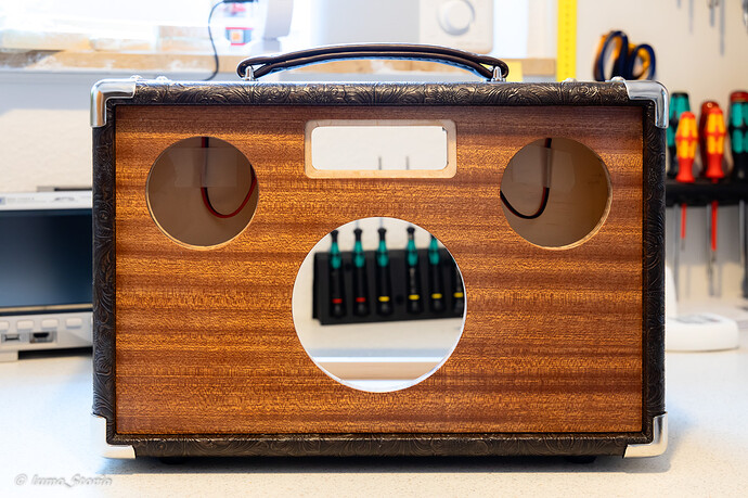
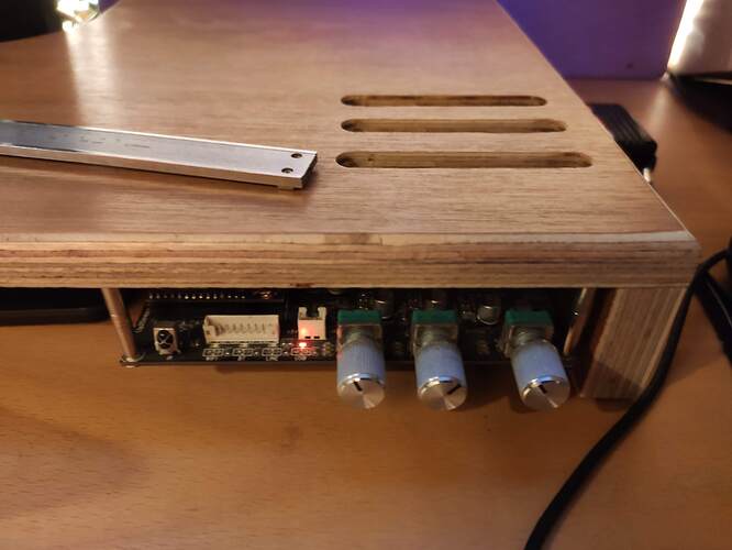
The woodworking part was not that complicated - glueing the sides together and covering them with brown structured Tolex, routing holes in front and back for speakers, radiator, and control panel, veneering front and back in Mahogany, and adding a handle, some rubber feet, and cabinet corners to give it a vintage “guitar amp”-ish look. Afterwards, the shell looked like this:

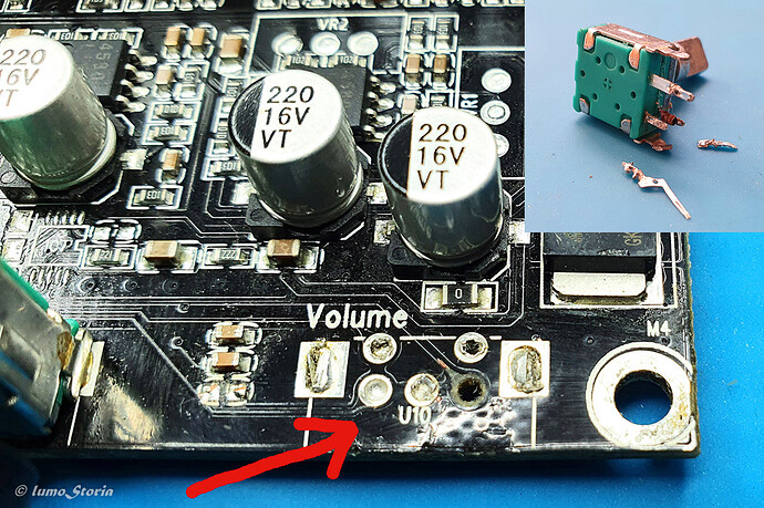
Then, I had the “glorious” idea to unsolder the volume encoder from the Arylic Up2Stream board (to use it in my own control panel) - and failed miserably.


(Without words.)

My kudos to the Arylic engineers for the robust design - the board still worked perfectly with the little flaw that the volume could only be controlled via App or remote control now - since I destroyed the encoder (and some part of the PCB) :weary:.

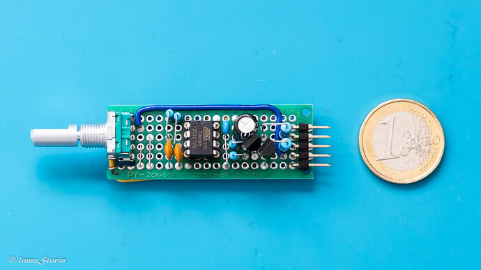
Only afterwards I learned that the board has a very handy 9pin breakout connector that allows, beside other things, to connect an external volume control. At least, if you can teach your volume control to provide a voltage impulse of intensity A for “volume down” and intensity B for “volume up”. Unfortunately, none of the volume encoders I know will do this, instead they just return a noisy 2-bit Gray code and let you figure out what they want to tell you. To solve this problem, I used a small microcontroller (ATtiny 85) to decipher the encoder response and convert it to the voltage impulses requested by the Arylic board. I put the encoder (a new one since I broke the original one during my desoldering failure), the microcontroller, and some more electronic components on a small piece of PCB, connected it to the Arylic board and - it worked :astonished:.

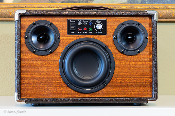
This success encouraged me to design a small control panel for the volume control, the mode switch, the mode LEDs (Line In, USB, WiFi, Bluetooth), the power/WPS switch, the Play/Pause and Next buttons, and the infrared sensor. All of these functionalities (and more) are provided by the 9pin breakout connector mentioned. One tip if you also want to use this connector: The Arylic manual just says “PH2.0-9P” but the correct name of the needed female connector is “JST XH 9pin” (pitch 2.54mm). Since crimping these small connectors can be a nightmare I suggest to buy the connector with pre-installed wires.

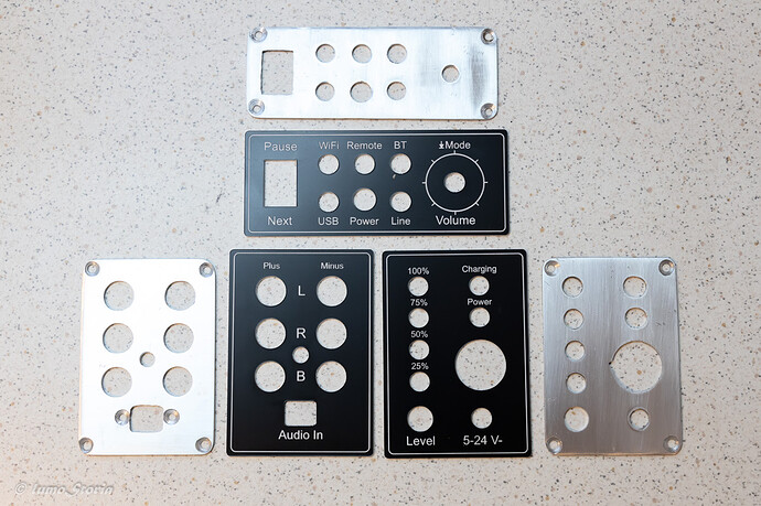
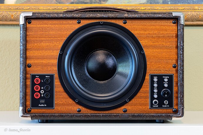
Here’s the control panel (goes to the front of the boombox), the audio in/out panel, and the power supply panel (later two go to the back). I didn’t find a better (while still affordable) solution than using a two-layer approach. The inner layer is hand-made from 2mm aluminium, the outer layer is laser-cut from 1.5mm acrylic. Unfortunately, the acrylic was not stable enough to use it as only layer.

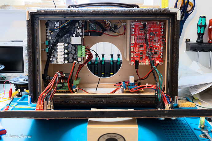
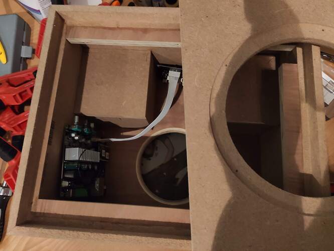
Now, everything was ready for final assembly. Here’s a picture of the interior of the boombox (with speakers not mounted yet):

In the upper left corner, there is the Arylic Up2Stream Amp 2.1 board. In the lower left corner, there is a DIY relay-based speaker control board. In the upper right corner, there is a Dayton lithium battery board holding five 18650 batteries (not visible because mounted underneath the board). In the lower right corner, there is a DIY power supply distribution board.

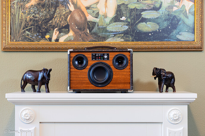
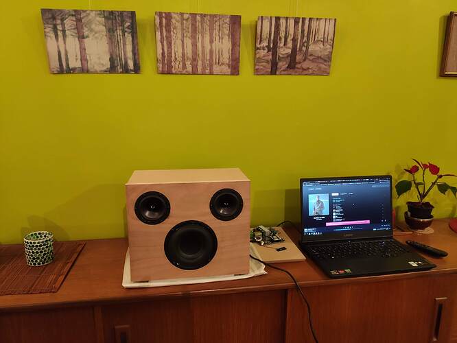
After mounting the speakers and screwing on the back, the boombox was finished. Voila :grinning::

Despite some setbacks (for which I take the blame), it was a pleasure to build my boombox powered by the Arylic Up2Stream Amp 2.1 board. What sets it appart from other amplifier boards I know (beside the ability to adjust its acoustic and control behavior using the ACP Workbench) is the breakout connector that allows you to design your own control panel freely, just based on the space constraints and aesthetic rules, not on the form factor and control layout of the board itself. Kudos for this.

Finally, if I may also express some criticism towards Arylic: For a board that powerful, the manual is definitely to short, leaving out certain aspects especially important for DIY makers. For example, it would be nice to state the correct technical names of all connectors on the board so that you can find the necessary counterparts without trial-and-error.

Hope this presentation of my DIY boombox was of any use to you.

Best regards,
Sven
14 Likes

Nice Boombox you have created!Looks very nice.
I also use an external volume encoder, but I got the one Arylic sells which can directly connect to my AMP 2.0 with cable, works pretty good too.

I know that Arylic sells a button board that includes Volume-Up and -Down buttons. However, in the front of my boombox, I only had space for a 3x10cm cutout to squeeze in all controls. In comparison, the Arylic button board looks gigantic. I also prefer a Potentiometer-style control over buttons.

Of course, the easiest way is still to desolder the volume control from the Arylic board and just connect it via wires. At least, if you are a desoldering guru (that I’m definitely not, as can be seen from the pictures). Wouldn’t try it again without a professional desoldering gun.

Technically Excellent, Passionately Built and Beautifully Photographed. Nice One @EthanEsrah :slight_smile:

Very nice work there and as I mentioned in my post, unlike me, I can tell you really know what you’re doing.
Well done. :+1:

Nice build!
I am making something very similar, I am a bit concerned about thermals (only using the Arylic amplifier board as electronics).
What are your thoughts on thermals? Doesn’t all those electronics get too hot?

Hi Tobias,
To be honest, I didn’t think about thermals when I built my boombox. As a class D amplifier, the arylic board shouldn’t produce too much heat. Also, despite the very nature of a “boombox”, I use it at moderate volume levels most of the time. Since the boombox is completely closed (and wood is a good heat insulator) it’s hard to say whether it gets hot inside. But even if it would get hot there would not be much you could do about it (except from not putting amplifiers in speaker boxes). Even if you do not use a closed box with passive radiators but an “open” one with port I doubt that this would transport much heat (if there is any) to the outside.
I would not worry too much about thermals and just start building… :wink:
Regards, Sven

Thanks for your quick reaction.
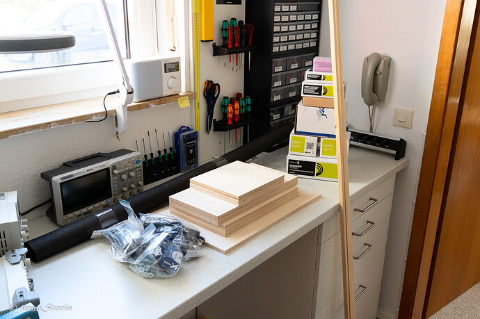
I am building alright, I guess I can start doing some tests next week:


I wanted to make a little housing sealed inside the box with vents to the outside, kind of what I did as a quick solution on my desk:

But it gets a bit complicated for such a small space, especially because I wanted to keep everything easy accessible. I guess will do some thermal testing. In the end it is meant as a gift for my sister, so I want everything clean and safe. I did build some small wooden enclosures for the same amp in the past, also vented because they could get pretty warm to the touch, not sure about the thermal limits.
Pretty funny how be both ended up with pretty much the same idea, same drivers, same passive radiator :grinning_face_with_smiling_eyes: My build will be little less complicated though.
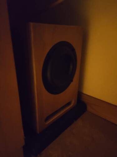
How is yours sounding?

Actually, the design was not my idea. It’s a mashup of the Dinas Boombox design of 123Toid and the Executive Boombox design of Parts Express, adjusting the dimensions to my needs and adding a better amplifier.

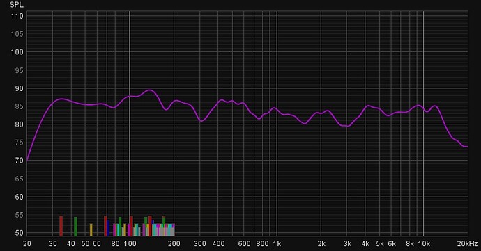
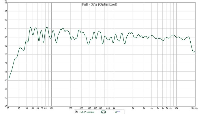
I’m not a HiFi enthusiast, means, I don’t have much comparison, but for me the box sounds quite good. I’m not finished yet with the final tweaking of the sound. I tried several settings in ACP Workbench and also experimented with the weights of the passive radiator. The following diagram shows the frequency response of my current setup:

I have heard that others got the bass down to 35Hz for a similar box but I only got it down to about 42Hz. Not complaining, I think this is still OK for a box of only 10 liters.

Would be nice if you could provide some more information and pictures when you’re finished.

Regards, Sven

That frequency response is looking pretty good :+1:
I think you should add some more weight to the passive radiator, according to the parameters I used in winisd, it should be more like between 70 and 90 grams, I have no experience with passive radiators so I might be wrong. I did build some bass reflex boxes with the same driver though, they surely hit 35Hz, but bass response is also heavily depending on the room and placement in the room, in my experience those little Tang Bands struggle in bigger rooms.
Bass reflex underneath my desk:


frequency response I measured a while ago, think I changed some things already since then (with two little two way boxes I made on the desk):

I have another question though, as I don’t really like the little add-on board for controls, can I just use OFF-(ON) switches for the controls instead? You (and others on the forum) talk about it but I am not sure I understand and the information is somewhat conflicting.

I surely will post some pictures and information when finished, no problem.

Greetings,

OK, 70 to 90 grams sounds like a lot of weight. I tried several smaller weights, the highest being 37 grams (stayed with that one). Maybe, I should have gone a bit higher. At the time I tried it, all hardware stores in Germany where closed due to the pandemic and I did not have appropriate washers. So I ended up using old coins from my travels (Costa Rican coins worked best because they are quite heavy :grinning:).

It is not a problem at all to use switches instead of the add-on board for the controls. I also did it in my boombox.


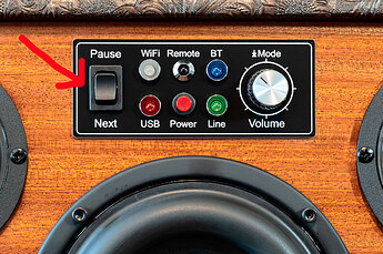
I used a pushbutton rocker switch for Play/Pause and Next. Would have used more switches but there was not enough space. The thing that is important here is to use switches of pushbutton-style. What the Arylic board expects is just a short impulse of a certain voltage, not a constant voltage level.

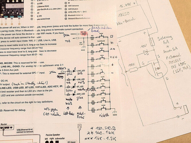
You can look up the correct value of the resistor (R60…70) you have to connect to the switch to control a specific functionality.


One important remark: You must not install resistor R47 (the one marked in red in the schematic) since this resistor is already installed on the board. This is an error in the schematic that led several people (including me) wonder why the values of R60…70 printed in the schematic did not work :thinking:. They did not work if you added your “own” R47 because this shifted the voltage levels. Although this error is known now it might still be a good idea to put together your control circuit on a breadboard first.
Regards, Sven

2 Likes

Wow, thanks for the information man, that’s very helpful.
I have the button board, so I can use that as a reference too I guess.

Just did a test setup this evening, still a lot of work to do but I couldn’t stop myself to do a ‘quick’ test:

I would highly recommend to try some more weight (if you want to get lower), I think I used somewhere between 70 and 80 grams. The weights are a problem though, hard to find the right size, I ordered some washers online a while ago for way to much money, high quality though :rofl:
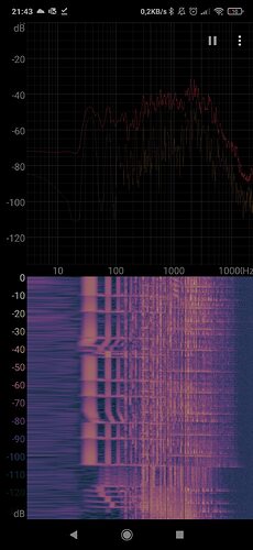
This is a song I know hits low I used for a quick measurement with my phone (“Canicule” by “Dub Panda”), it hits 35Hz:

I was pleasantly surprised how good it sounded already, without much tuning (just pushed the the left and right channel 5db down and moved the crossover to 125Hz instead of the standard 110Hz), without any damping and loads of other little things to do.
Greetings

This looks fantastic! Can I ask how you designed the front panels for the encoders (the aluminium and plastic parts)
Can I be cheeky and ask to share the CAD files for them?

Many thanks

David

Hi David,

Welcome to the forum and thanks for the positive feedback on my project.

The front panels are very specific to the available space on the front and back of my boombox and also on the measures of the controls I used. The space was very limited and I tried to squeeze as many controls into it as possible. Took me several iterations and a couple of panels that went to the trash can. With the knowledge of today, I would even make some different design choices (like using a single RGB LED instead of several ones for the display of the active source). Therefore, I don’t think that there would be much reuse for my design.

For the aluminium panels, I have only hand-made sketches. For the plastic panels, I have Inkscape files but again, they are very specific. Therefore, I would refrain from sharing them, sorry for that.

Just for a rough guidance: The panel on the front is 45x110mm, the panels on the back are 85x60mm each.

Best regards,
Sven

1 Like

Hello Sven! Beautiful work!

I have a, hopefully quick question for you, I am particularly interested in your control panel. I’ve worked with aluminum for this as well, but I never got to figuring out how to print a panel with text for it.
1.5mm acrylic… So, you painted the back of the acrylic white, the front black and then lasered the text on the black surface (thus revealing the white back)?

Thank you for your time! You really nailed this boombox!

Thanks for the positive feedback, Paul. I’m feeling honored that you thought I made the panels by myself :wink:.

In general, you described the process correctly except that you do not need to “paint” the acrylic. There is a special two-layered acrylic called Transply (don’t know if this is a brand name) with a thick base layer (in my case: white) and a thin top layer (in my case: black). Other color combinations are also available.

I drew the control panels in Inkscape and sent it to a sound equipment shop here in Germany that also offers laser engravings. They charge you per “sheet” (75x300mm, 150x300mm, …) and if you manage to squeeze all panels onto one sheet (what I did) the prices are quite reasonable. Here’s a link to the shop: https://www.tube-town.net/ttstore/custom-shop-faceplate-standard.html

Unfortunately, the arcylic alone is not stable enough to mount the switches, etc. directly onto it (at least the 1,5mm version I used). Therefore, I had to make additional aluminium “base” plates to add the necessary stability. I would have preferred a solution with only one panel (like printed aluminium) but this would have been too expensive.

Cheers, Sven

1 Like

Lovely. Thanks for all the info. I’ll be looking to build something very similar and those panels were the one thing that had me scratching my head. I do own a laser engraver, and something like a Cricut Maker might be able to cut into the acrylic like a small pseudo-CNC would, so you’ve really shed some light on what the project could look like and how to get there, I appreciate and salute you for that.

I’ll look into this transply thing. Thanks again and kudos for the awesome work!

Hi dear! to your pcb input for the ADC or for the encoder?

the microcontroller ATTINY85 converts the gray code into a signal for the ADC, right?

Hi Artem,
Yes, the microcontroller converts the gray code into the ADC signal. The ADC pin of the connector can be used to control eleven different actions (beside volume up/down things like play, pause, prev, next, and input mode selection). The actions are identified by different voltage levels. As far as I remember, volume up is about 1,2V, volume down is about 1.5V. What the microcontroller does is to create a small impulse at one of its pins for each “click” of the encoder in clockwise direction (volume up) and the same at another pin for each “click” in anti-clockwise direction (volume down). Each of these pins is connected to a transistor which creates the respective voltage.
In hindsight, this solution is a bit over-engineered :roll_eyes:. As far as I remember others have just soldered wires to the original encoder on the PCB and added another encoder in parallel. This reduces the risk of damaging the PCB in the attempt to desolder and reuse the original encoder (as it happened to me :sob:). If you don’t need a rotational volume control it’s even simpler since you can just use two push buttons and two resistors to control the volume via ADC pin.

This I have not heard about that… Is the C27 still required?