I designed my own PCB with ADC-Keys to control the media playback, but unfortuantely none of the buttons are working properly.
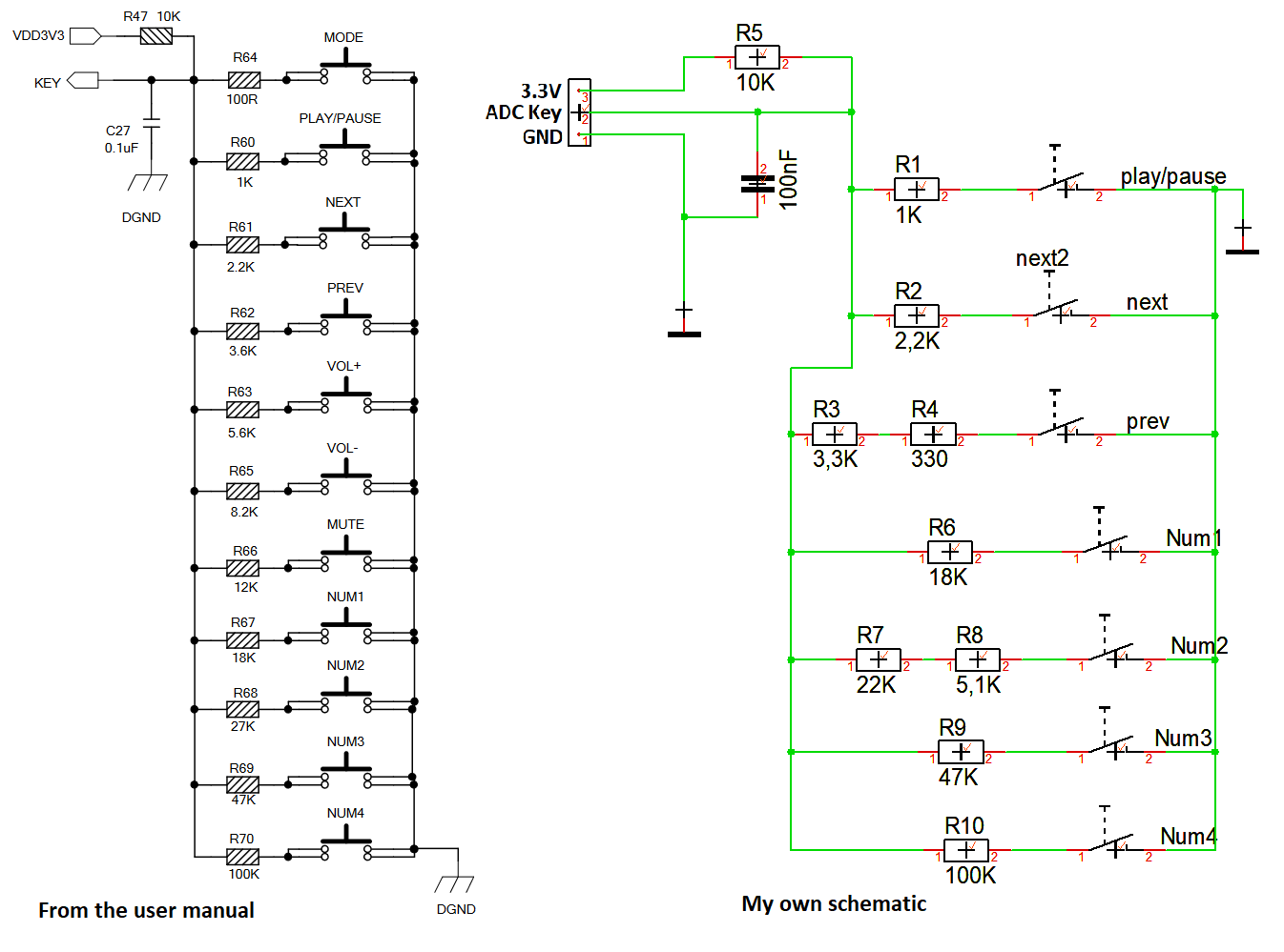
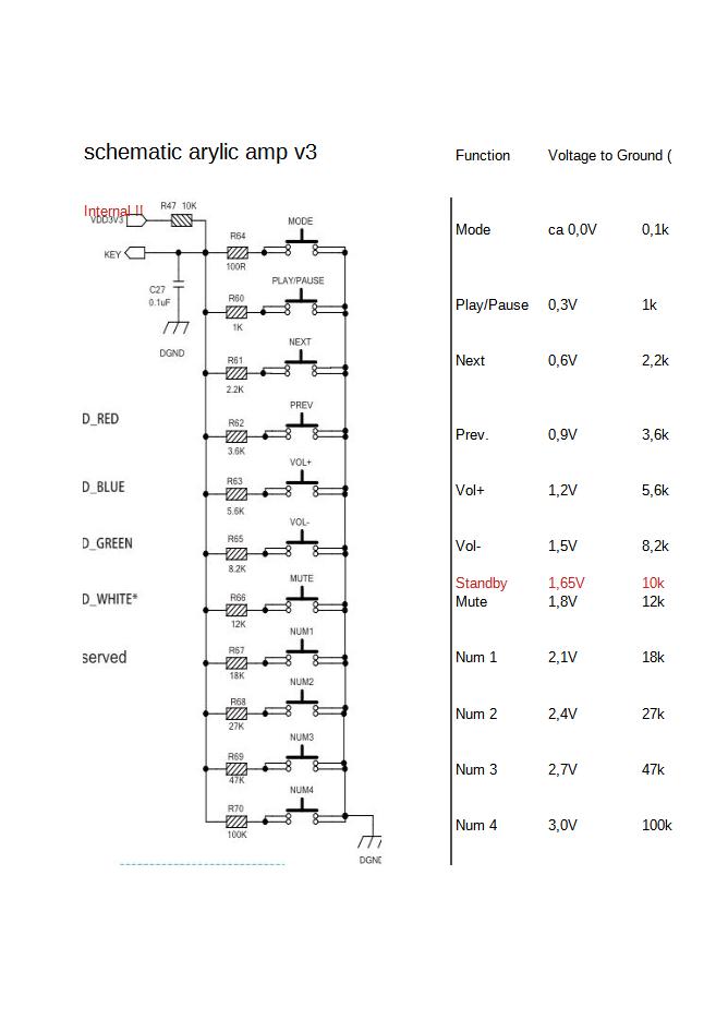
Based on the schematic in the AMP2.1 User manual, I made my own schematic with some of the ADC Keys (see picture below). Since I do not have a 27K resistor I used a 22k+5.1k resistor in series and instead of a 3.6k resistor I used a 3.3k+0.33k resistor in series, thinking these values should be close enough for such a voltage divider.
But unfortunately none of the buttons are working as they should be. Some aren’t detected at all while some are being detected as something else.
Num1-Num4 are not working at all, even though I have presets defined in the 4stream app and I can start theese favorite presets from the app.
3.3V is hooked up to the pin on the very left, GND to the second pin from the left and the output of the voltage divider is hooked up to the second last pin.
Hi!
I tried using buttons on Up2Stream HD. Perhaps the resistor R5 (10K) is already on the board? In my case, I just connected the resistors through the buttons to GND.
Thank you for the response! After reading the other thread it seemed promising, that I just need to remove (or basically short) the 10k resistor on my board. Unfortunately this did not fix the problem for me. After doing that, none of the buttons are working anymore. Before I could here a beep on every button press, now I don’t here any beeps anymore and also none of the buttons are doing anything now.
When I just remove the 10k resistor and don’t bridge the contact pads, the 3.3V Pin would not be connected anymore, since it is in series with this resistor.
When I remove my 10k resistor and bridge the solder pads of this resistor, none of the buttons are working anymore. Without my 10k resistor, I measure 3.285V on the ADC Key all the time. Both when I press a button or when I don’t press any button.
When I add my 10k resistor back, the voltage on the ADC key varies depending on which buttons I press. Just the behaviour you would expect from a voltage divider.
I also tried to find the 10k resistor on the amplifier board and verify the resistance, but I couldn’t find a 10k resistor which is hooked up to the 3.3V pin so far. It’s quite difficult to follow the traces on the PCB to find it.
It’s easy to check for a resistor on the board by shorting ADC_KEY to GND with a 10K resistor. If at the same time there is about 1.6V on ADC_KEY, then there is already a resistor on the board. Is this the behavior you expect from a voltage divider?
Thank you, with this example I finally got it I thought I still need the 3.3V pin and just that there would be a 10k resistor in line with the 3.3V pin, so I wouldn’t need to add the resistor afterwards … but I don’t need the 3.3V pin at all since the ADC pin already has a pullup resistor. Got it Now it is working fine.
Glad you already found the Solution.
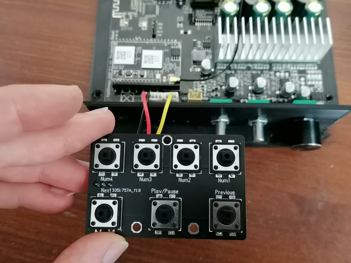
Your PCB looks pretty nice!
Where did you order this and how much did it cost?
I am thinking of getting my own, just with JST connectors instead of the Buttons soldered on directly.
I ordered them on JLCPCB for 2$ + shipping for 5 of them But I think they applied a coupon, normally it would probably be like 4$ + shipping. Still very cheap. I also made a PCB with a headphone output, that automatically switches between the speaker and the headphone output when you connect the headphones.
I might need your help as well. I am hoping some of you still be around after 3 years.
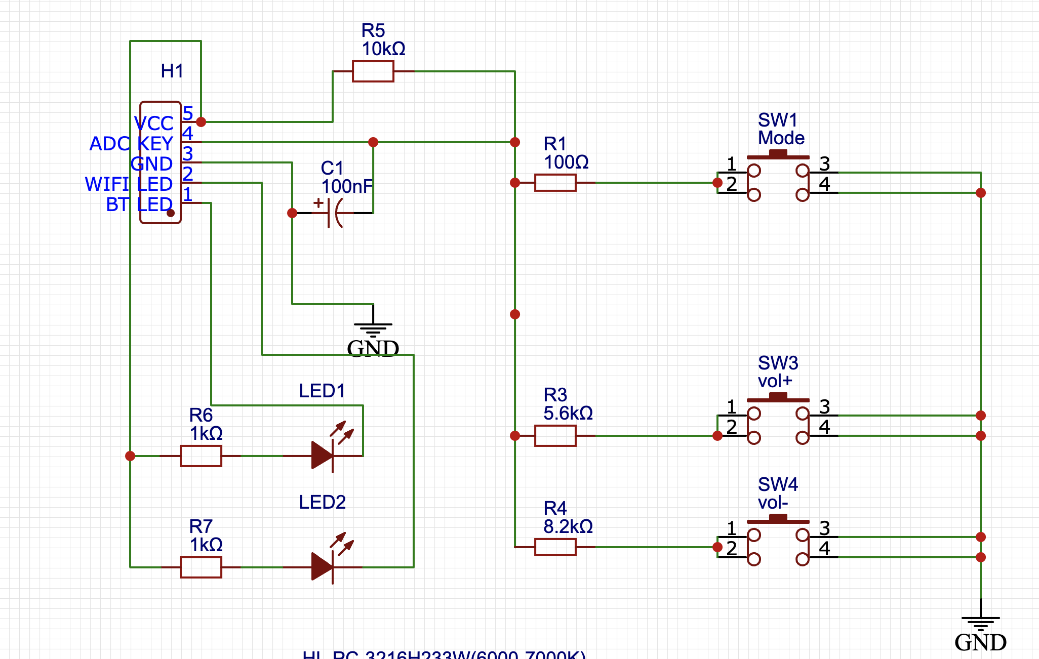
I’ve been reading your comments and tips. However, I am not able to control the volume. The mode button and LEDs are working, but the volumes are not. Here is my PCB board diagram. I was using it for Up2Stream mini and pro. Can you please take a look at it?
Thank you again for your help above. That works nicely!! This forum motivates me to do something different.
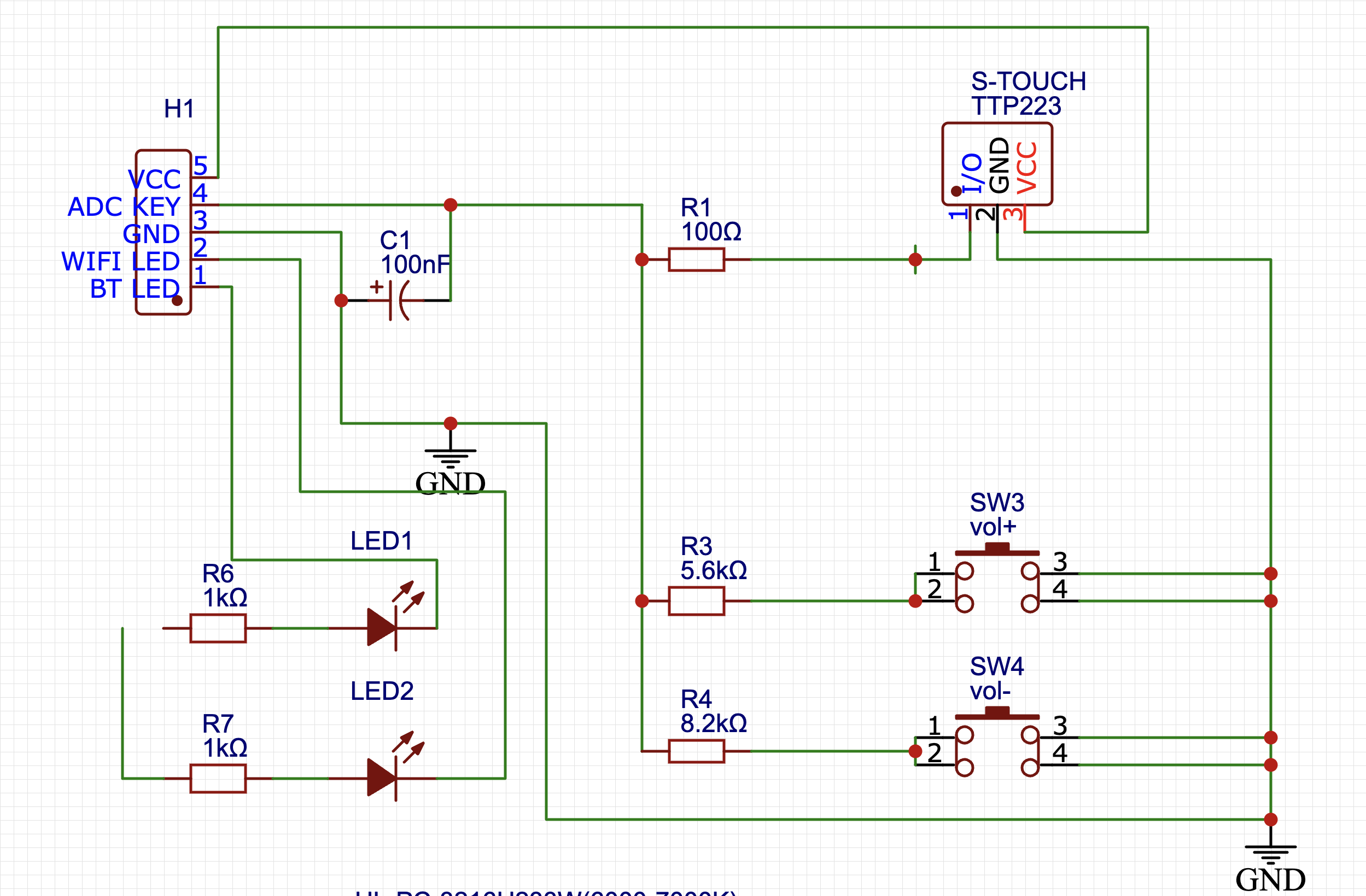
In my current project, I wanted to replace the buttons with touch-capacitive TTP223 buttons because the regular buttons don’t look very appealing.
Like this topic
However, I’m not getting any signals. I shared the diagram with you. Where do you think I might be making a mistake?
PS: TTP223 is in default mode. Not in an A or B or both.