Iv’e been a hobbyist speakerbuilder from germany for a few years now and i’ve wanted to share my latest project here with you today.
This was my first time ever using an Arylic product and i must say that i am really amazed of the Up2Stream AMP V4 that i’ve used in this build.
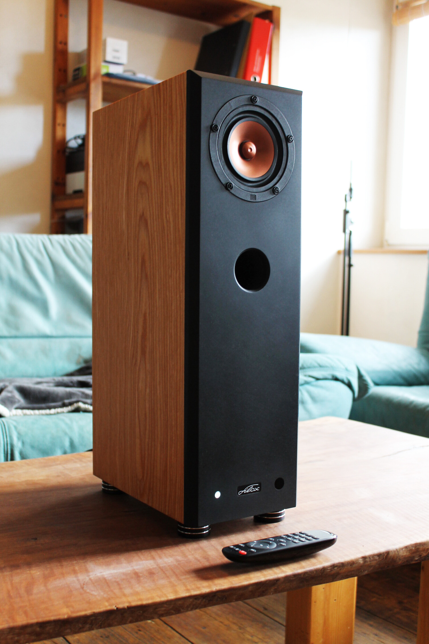
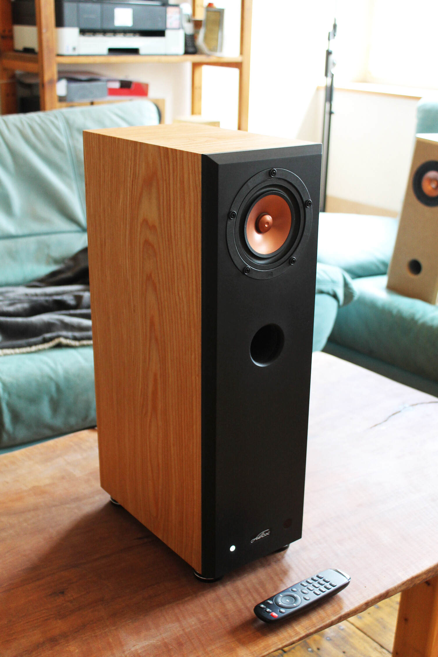
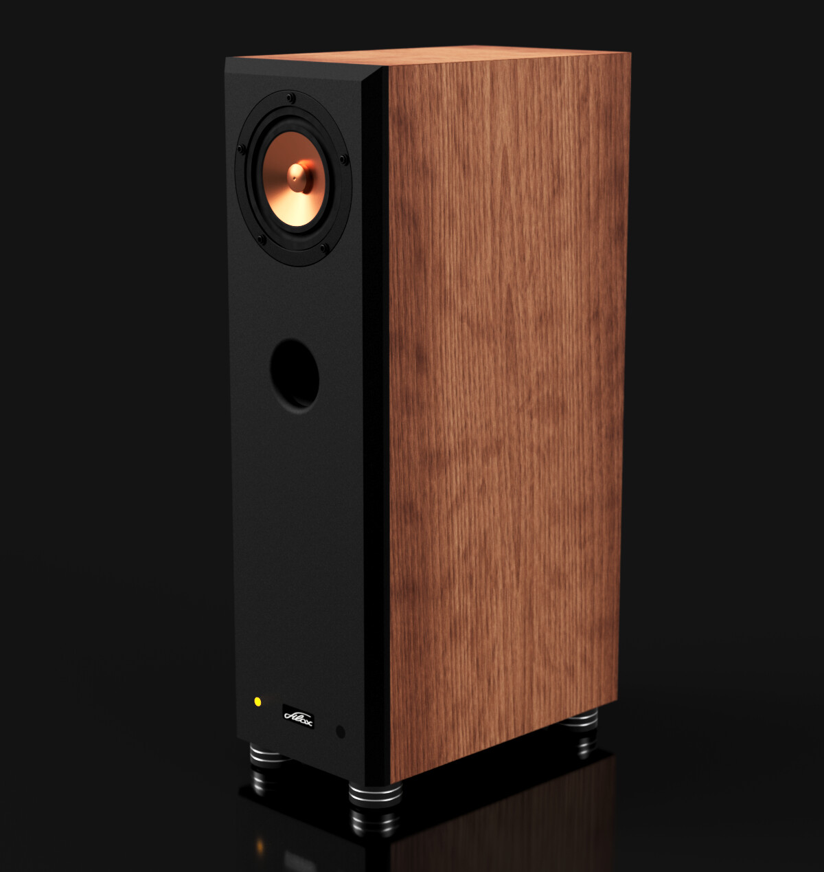
This is a fullrange speaker build in a bassreflex enclosure of 12 liters. They have an f3 of about 48 Hz which is pretty nice considering it’s such a small fullrange driver. Also i am amazed at the highs this speaker is producing, they disperse very nicely throughout the room which is rather atypical for a fullrange driver.
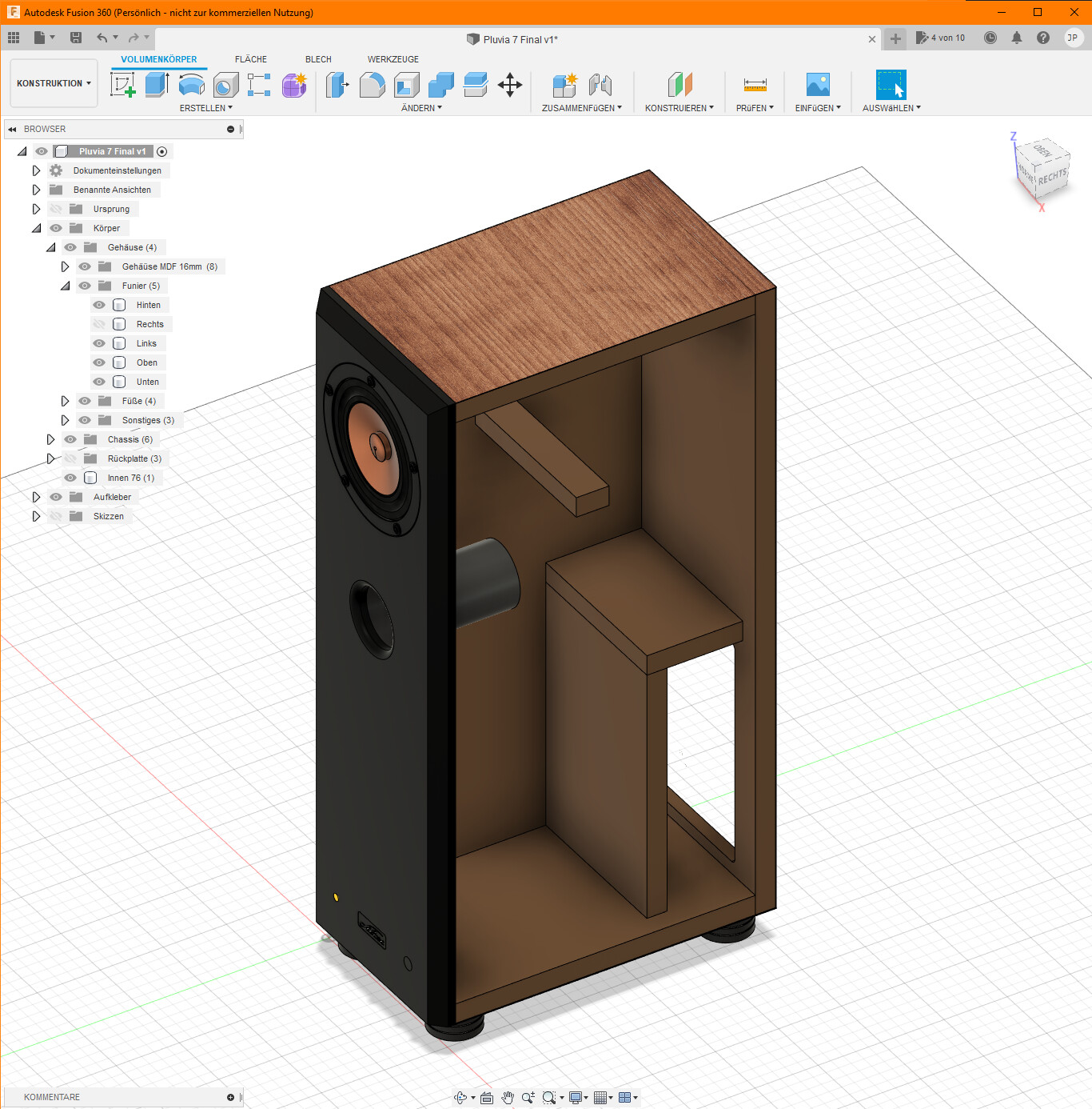
I used DATS V3 to measure TS-parameters, VituixCad to simulate the enclosure, and Fusion 360 to make the design (you can see a screenshot of that further below).
The enclosure is build from 16mm mdf (which is pretty expensive in these times), the front is made from black 16mm mdf and i’ve used saraifo cherry veneer. The front is finished with hardoil which has been sanded down and reapplied several times to create a matte finish. The bassreflexport is a simple piece of hdpe pipe cut to length. I’ve rounded over the outlet with a 10mm radius bit. On the inside of the enclosure there is a good amount of dampening material strategically placed behind and below the driver and port.
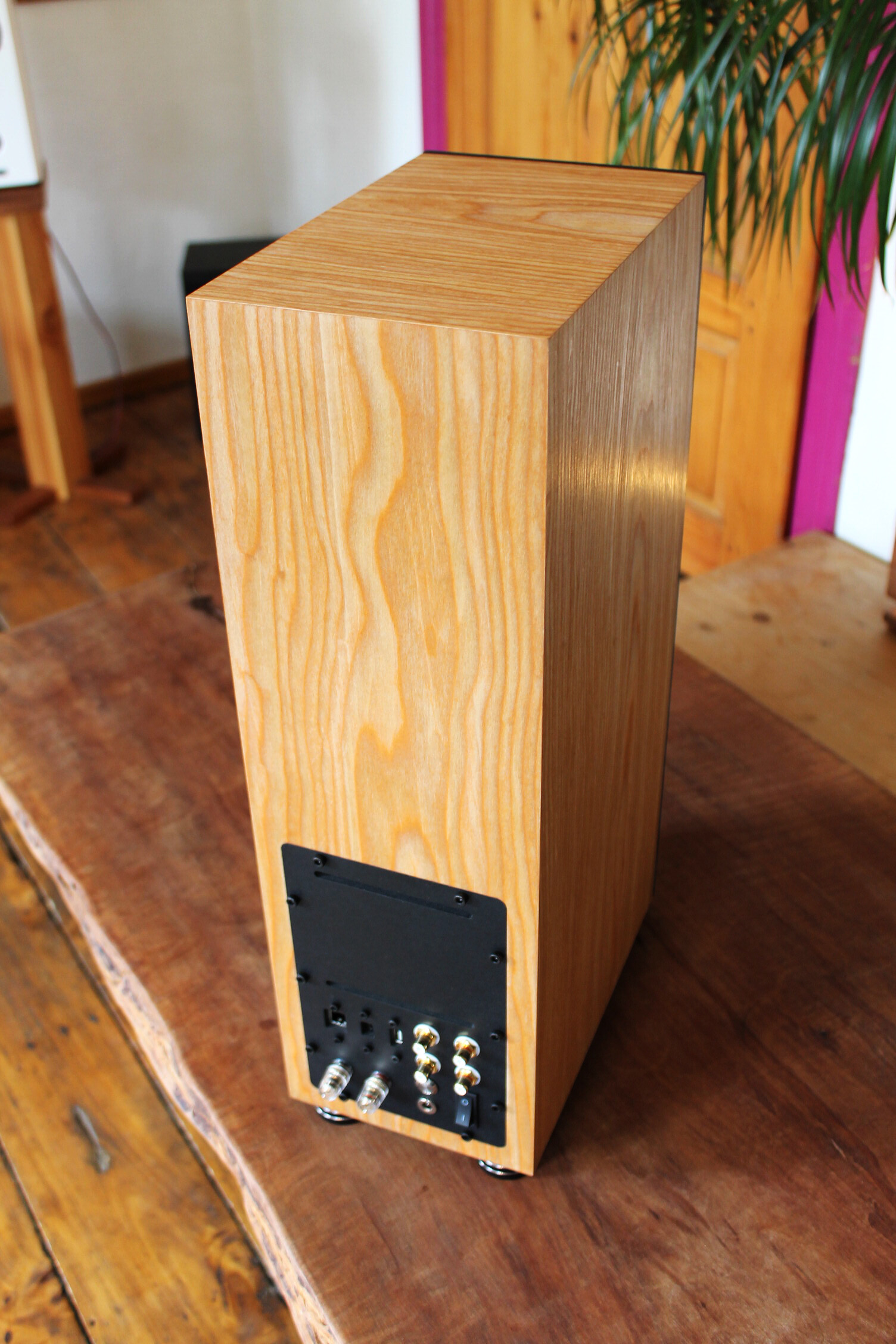
The backplate is also made from black mdf. Most parts have been cut with my diy cnc mill. Conviently i can make toolpaths for this directly from my fusion 360 design.
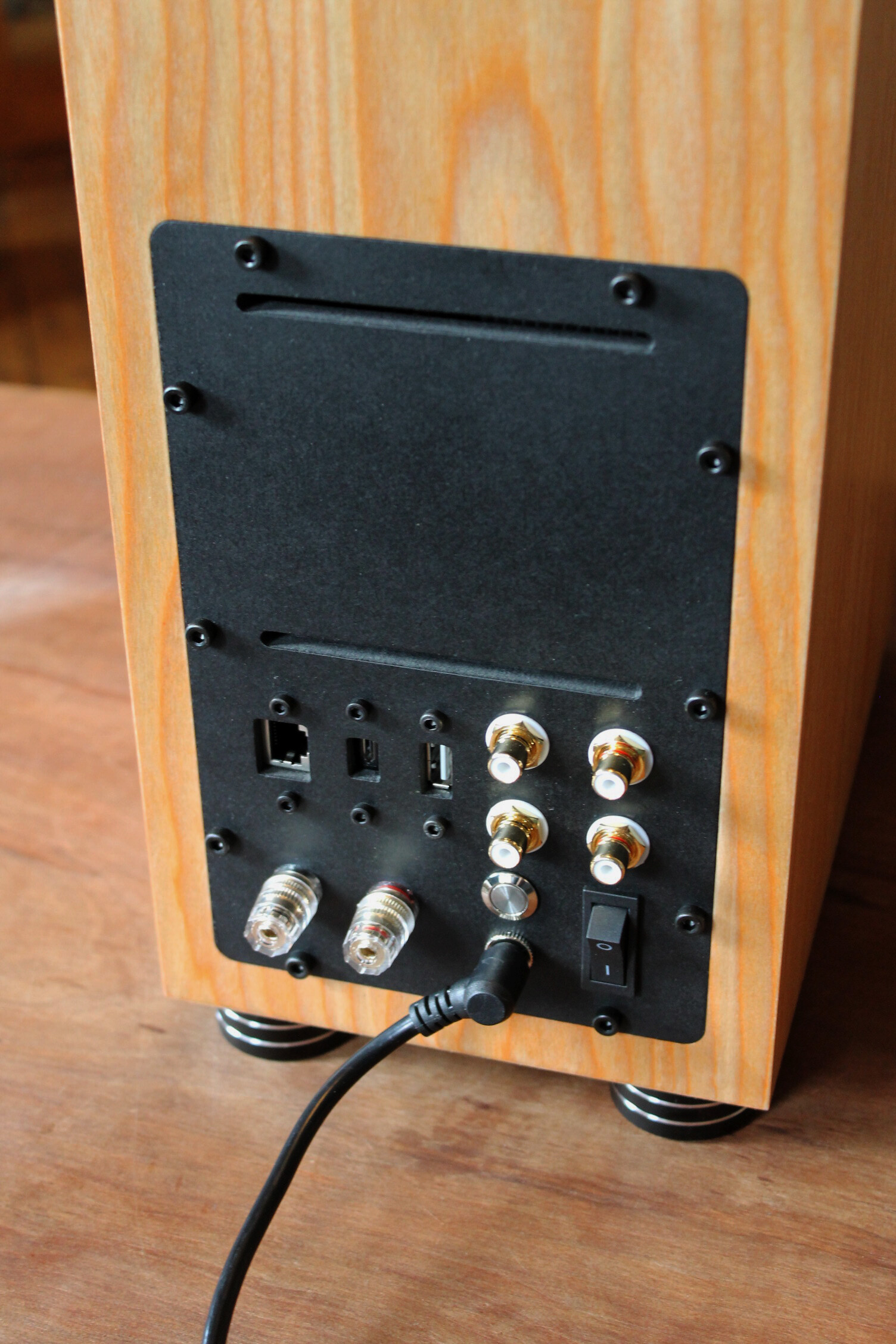
On the front of the speaker you can see a round piece of black plexiglas which is infra red transparent. behind it sits the ir reciever, which i extended from the board - as well as the rgb led on the left. On the backplate you can see the various inputs which also have been extended, mostly with cables that feature a panelmount (Usb, Micro Usb and Ethernet). Then theres Chinch connectors for analog input as well as the Speaker Out for the left speaker. Also i’ve put a mainpowerswitch and an extended wifi/rest button. The speakerfeet are solid aluminium with a rubberring on the bottom.
It was very easy to correct the speakers response with the onboard dsp. I measured the speakers response in room eq wizard with my Umik-1. Then i had room eq wizard calculate filters to flatten the response towards my desired target curve. The filters were then typed into the Main EQ in Acp Workbench. Now i took a measurement again to confirm and the response was looking great!
All in all setting up the DSP with ACPWorkbench was straightforward and pretty easy!
What i especially like about the Amp is, that i can put 6 favorites to the remote, so i dont even need to connect anything to the speaker to be able to listen music. I really like that you can change the name of the device to your liking (shows in bluetooth and wifi apps)and adjust nearly everything how you want it.
The many extensionports on the board make it easy to customise the speakers functions to only what you want and need.
Hey fi3ur,
tolle arbeit von dir und eine schöne beschreibung deiner detaillösung, kannst du noch den breitbänder genauer benennen? oder warum hast du den via DATS V3 nochmal ausgemessen? Dank und Gruß aus Erfurt! Jörg
Das ist ein Pluvia 7 HD von Markaudio. Prinzipiell messe ich jedes Chassis selbst um aus den gewonnenen Parametern das entsprechende Gehäuse zu berechnen.
Hi Janosch,
Congratulations, the speakers look gorgeous. I know what you mean regarding the wood prices, we should start making speaker cabinets from gold to lower production costs .
Since veneering the front and back of my boombox almost drove me to despair: What’s your award-winning technique? Using heat, pressure, or Pattex? Veneering first or cutting first? Thanks a lot in advance.
Best regards,
Sven
(Grüße aus der Rhein-Neckar-Region)
I used saraifo veneer (which is not like normal veneer - look it up its amazing stuff).
First i apply woodglue with a paintroller to both surfaces. While they start drying i heat my iron to max temperature (cotton).
After about 10 minutes the woodglue starts to become transparent and dry to the touch.
When its at the point that it wont stick on my finger anymore when touching it lightly,
i will put the veneer to the mdf. I put a sheet of bakingpaper on top of the saraifo veneer and then start ironing it with some pressure and i pay some extra attention to the edges. It only takes a minute or 2 and the veneer is applied.
Now i cut the veneer along the edges with a sharp cutterknife leaving a bit leftover and not cutting too close to the edge. Then i will sand down the remaining veneer with a very fine sandpaper glued to a pice of mdf (so its flat).
Hi Janosch,
Thanks for the detailed description. I checked SaRAiFo at the beginning of my project but then decided to use “normal” mahogany. The approach you described was the first I tried. I tried it at some test pieces and it looked quite good but when I noticed some cracks in the veneer. Maybe it was just faulty veneer, the iron was too hot, the humidity of the veneer was to high/low, or whatever. Probably, it was just me. My second attempt was to use just pressure but this did not work at all. Unless you have a (heated) veneer press, it is very hard to reach the pressure needed. Finally, I tried the Pattex method and it worked well (except for the fumes). Like you, I also used hardoil for the surface finish. Since I only veneered the front and the back and both are a bit recessed, at least the cutting of the edges was easy. I just used a trimming cutter (Bündigfräser).
Best regards.
Sven
Wow, Respekt! Ein wirkliches Schmuckstück ist dir da gelungen!
Zwei, drei Photos vom Elektronik-Innenleben würden mich persönlich noch interessieren.
Tolle Arbeit.
Wow, respect! A real gem you have done there!
Two or three photos of the electronics would interest me personally.
However, really great work.
Thanks, im happy you like it! The electronic part isnt even that interesting imho. Its just the board with a lot of cable extensions to bring everything to the backpanel. The only extrathing i did was extended the rgb led and ir reciever from the board
Hey, youll need a JST PH 2.0 cable to connect to the board. you can find the pinout in the user manual of the arylic amp. you will need a common cathode rgb led. put a 1k resistor before every anode connection of the led. Thats it


 .
.

