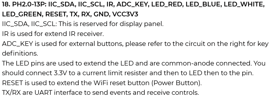
The common firmware for this board only support RGB LED, so all the RGB line would be activated for white. And for the PINs of extended, we reserved it for the condition of customizing firmware. I’ll find a way to configure this via API commands.
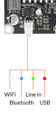
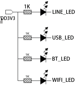
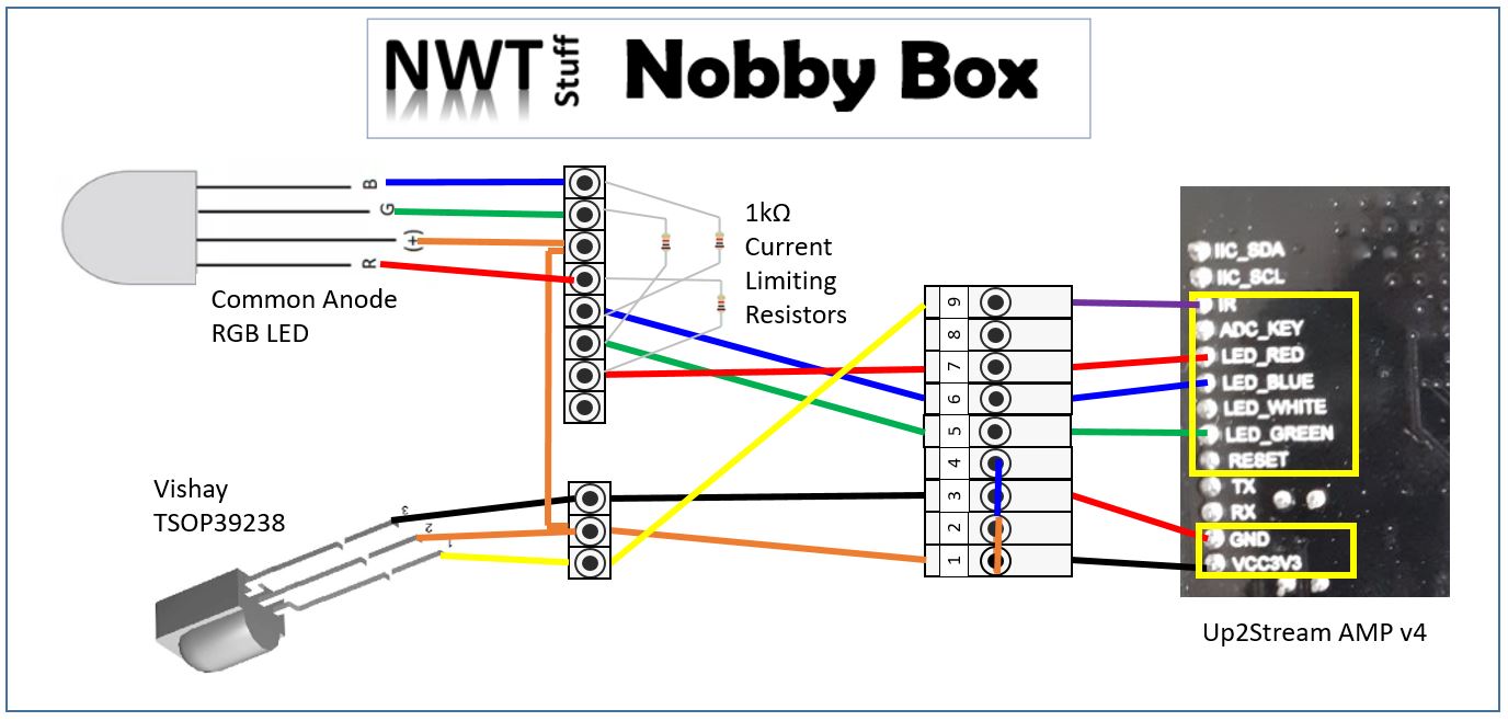
Same problem with a replication LED for the new Plate Amplifier. The JST-PH connector offers 4 pins: 1 (common anode) with 3.3V DC (VCC) and 3 for the cathode of R,G,B LED. So a 4 pin RGB Led (5mm) could be used to indicate the selected source on the front side of a speaker. Unfortunately this does not work because this common anode LED needs a Vf (forward voltage) of about 3 VDC to 4VDC (blue) to go into conduction. Even an SMD chip three-color LED has a Vf of 3.3 VDC and will not conduct either. The 1K current limiting resistor suggested in the manual will then not have to limit much more because there is simply no current.
Only some red Leds (low current) do conduct (Vf < 3 VDC) and light up sufficiently if a much smaller series resistor is used (VCC-Vf 1.2V/220R = 5.4 mA).
Moreover, the 3 pins (R,G,D) appear to be pulled to Gnd simultaneously, regardless of the choice of source. The Wifi module however needs a 5 VDC on pin 1,2. Without documentation it is risky to experiment further.
Why is that JST-PH 4 pin LED connector provided and how can it be used safely?
The connector for an IR receiver does work fine (with a standard type 38 Khz carrier 940nm wavelenght) and the Arylic remote control.
Thanks for your sharing.
I’m working on a 2.1 amp and this diagram doesn’t seems to work for me.
I’m looking to deport led’s to an RGB Led.
Have you tried this wiring on other board?
Hello,
I am having the same problem with source LEDs for the 2.1 plate amp. Did you have any luck? Line-in LED (using green LED) (pin 6)) is the problem. For instance if I am using WiFi that LED will light but soon after the green LED will light too.