English below
Bonjour à toutes et tous,
Je n’ai pas de formation spécifique, j’apprends par moi même en cherchant sur internet et en essayant.
Ma première découverte avec Arylic a été une bonne surprise. Je cherchais un moyen de me lancer dans le multiroom mais les solutions existantes étaient trop chères (Sonos) et ne permettaient pas de pouvoir réutiliser de appareils que j’avais déjà en ma possession.
Comme première approche j’ai acheté l’amp 2.1. Je voulais tester la qualité du son, la stabilité du streaming… et j’en suis très content.
Je vais bientôt l’intégrer dans un projet afin de “cacher” la carte dans une belle boite (je vous ferez part de ce projet lorsqu’il sera plus avancé).
Après cette bonne expérience je me suis lancé dans une création avec l’up2stream pro v3.
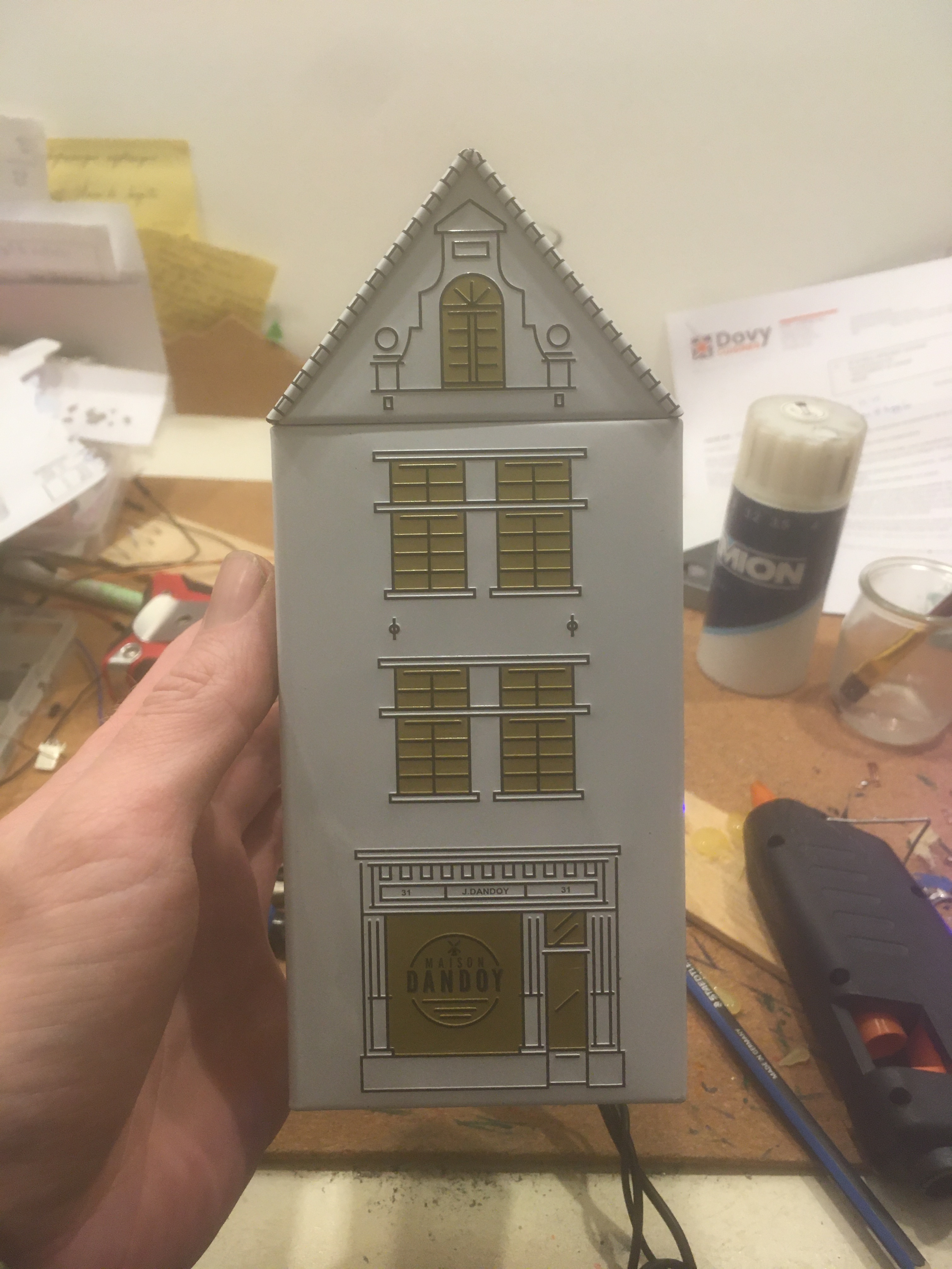
L’idée était de l’intégrer dans une boite de biscuit afin de pouvoir avoir un objet de décoration qui ne ressemble pas à un récepteur multiroom et qui puisse être installé à côté d’un ampli ou de baffles amplifiés.
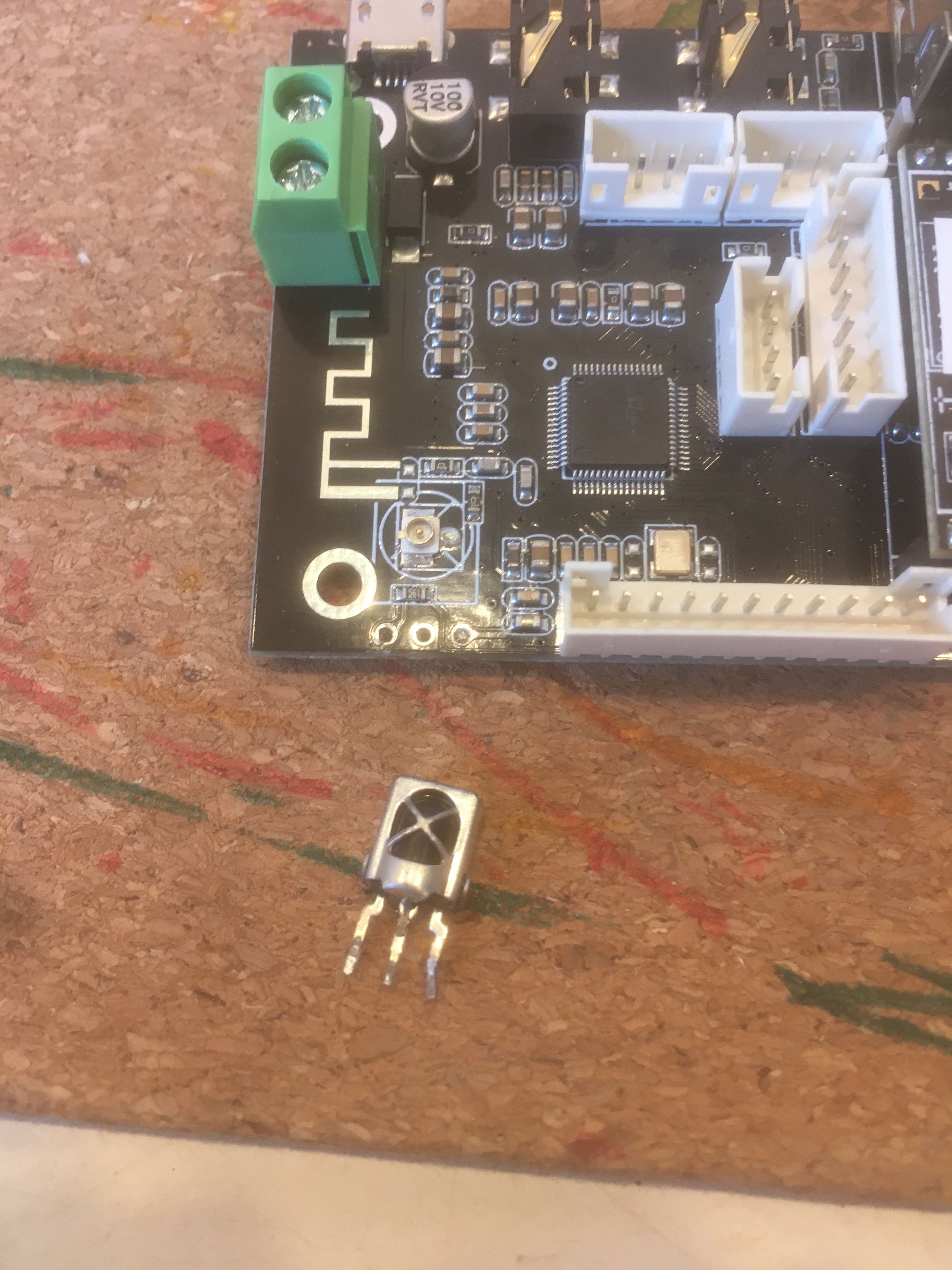
Pour pouvoir bénéficier d’un maximum des capacités de la carte malgré qu’elle soit enfermée dans une boite, j’ai désoudé le recepteur IR afin de pouvoir le déporter à l’exterieur de la boite.
C’était la première fois que je désoudais un composant d’une carte et cela m’a pris un certain temps pour être sur de ne rien abimer. J’ai utiliser une tresse à désouder, un pistoler à désouder et un fer à souder. En alternant différentes techniques, petit à petit, j’ai réussi à retirer l’élément. Les trous étaient bien vidés et simplement en remettant le recepteur dans son logement, j’ai pu voir qu’il fonctionnait parfaitement et n’avait pas été abîmé. J’ai un fer à souder de 30W et je pense que c’est insuffisant pour pouvoir désouder facilement et rapidement mais avec beaucoup de patience… c’est possible.
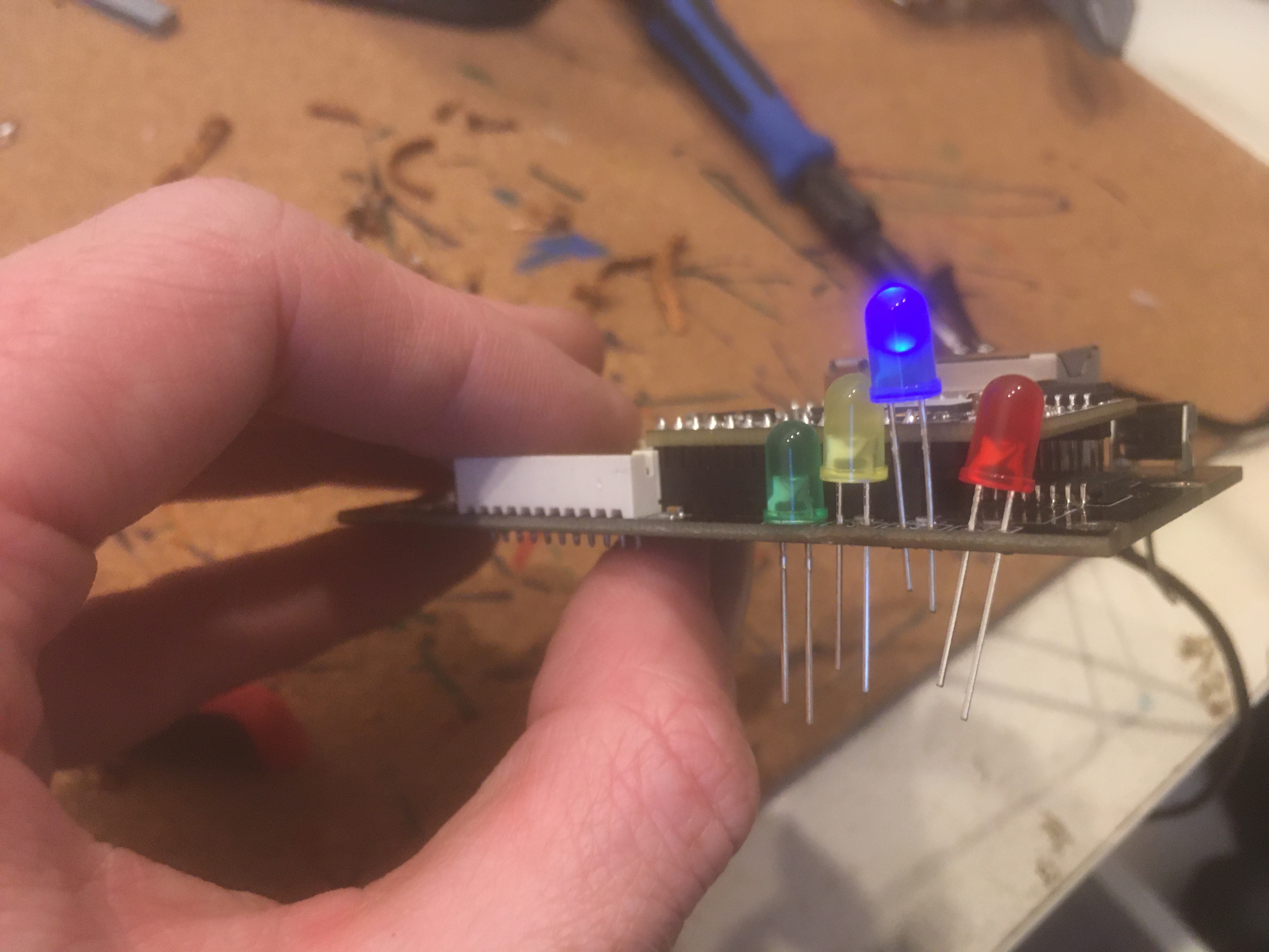
La deuxième étape a été de déporter les leds. L’opération est un peu plus compliquée et je n’ai pus retirer qu’une seule led fonctionnelle sur les quatre mais sans abimer la carte. De toute façon j’avais prévu d’autres leds pour les remplacer. Après un petit test, les soudures de mes cables de rallonges se sont faites sans aucune difficultés.

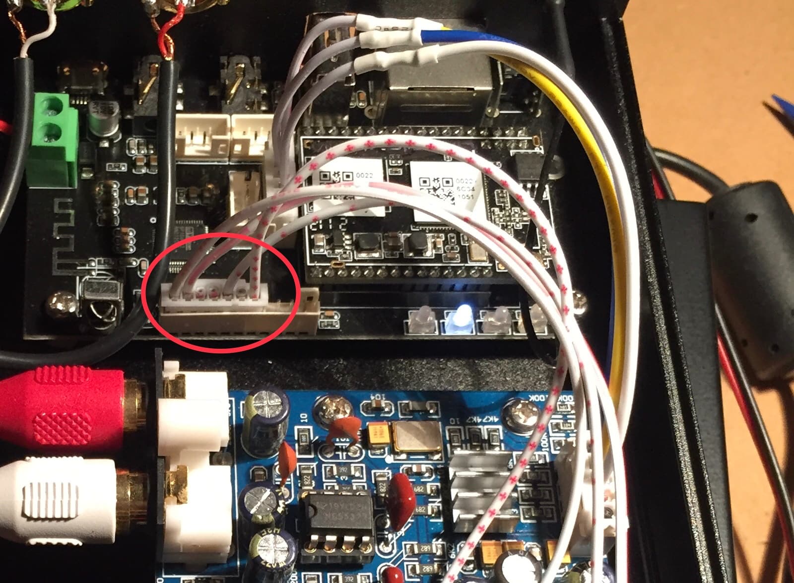
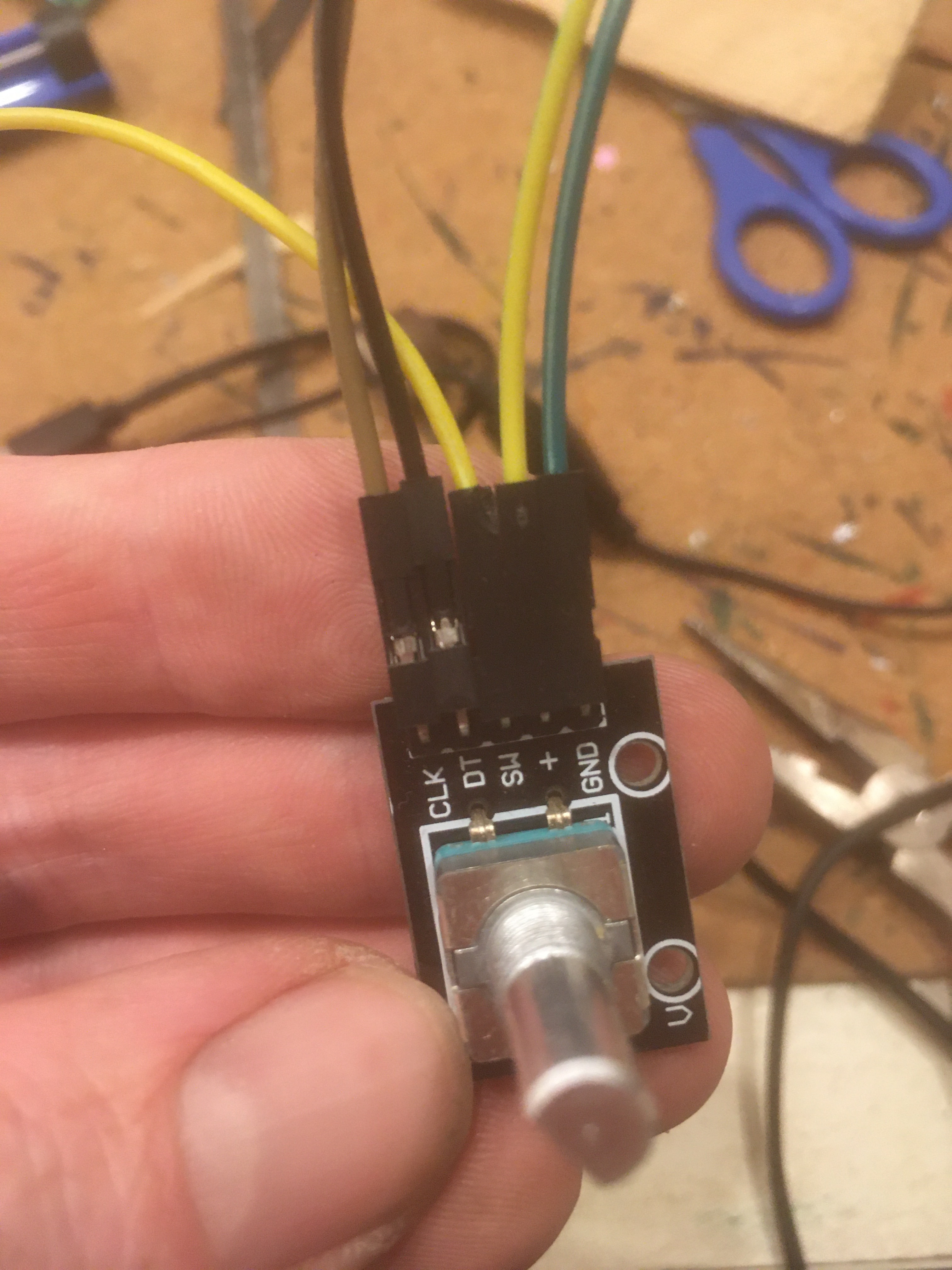
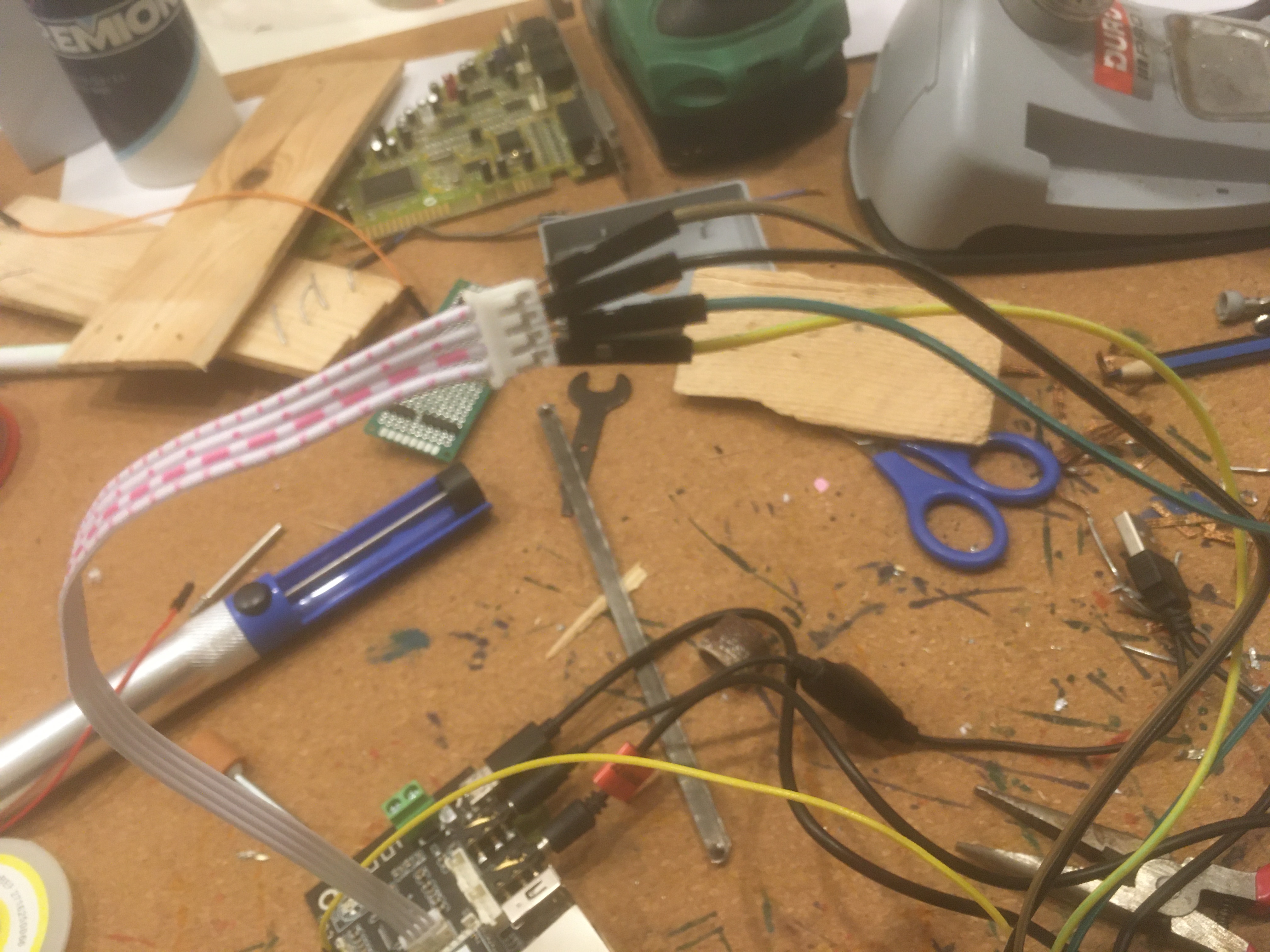
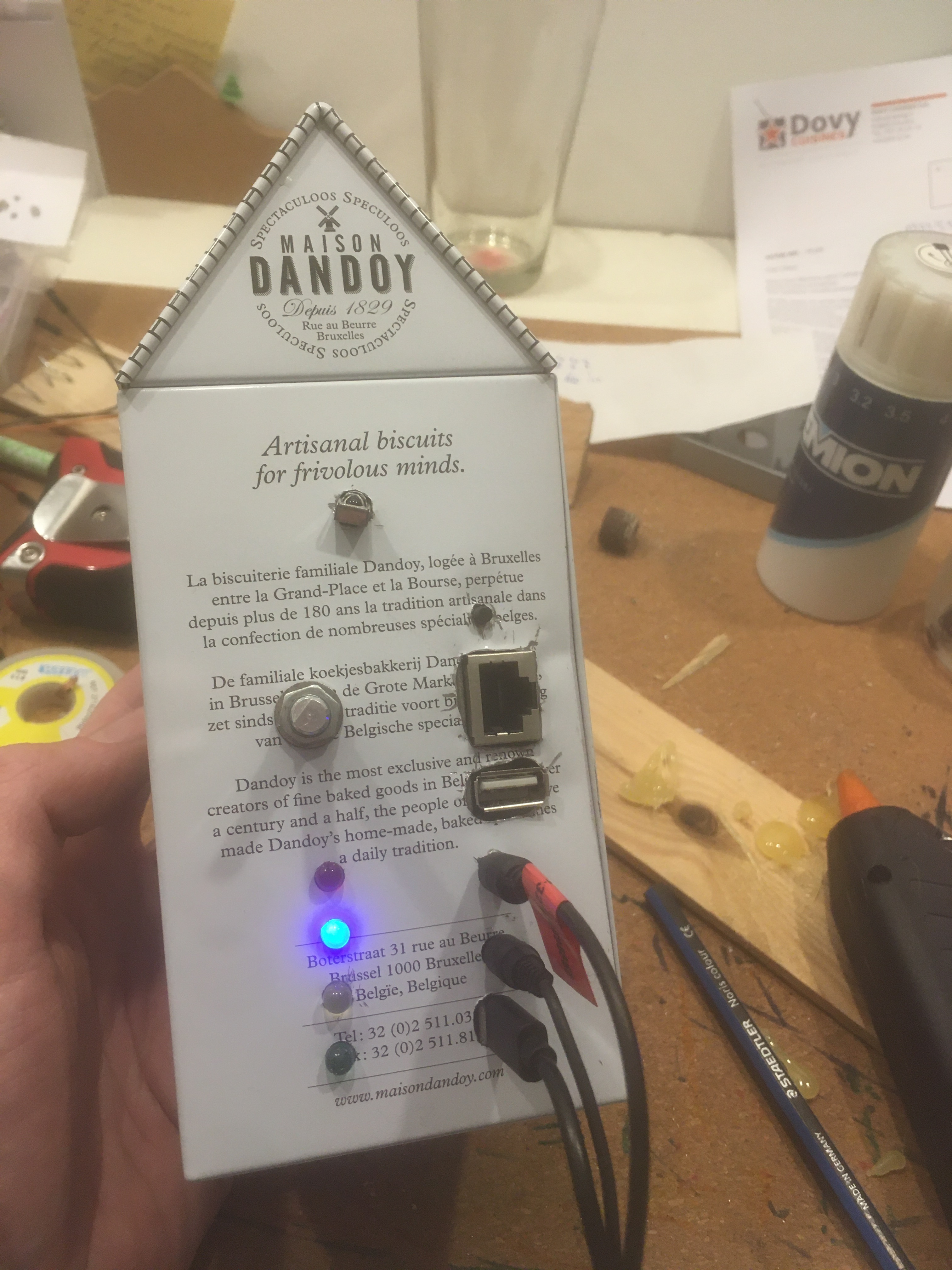
J’avais envie d’ajouter un bouton volume (bien que ce ne soit pas un ampli et du coup la plage de volume n’est pas très grande) qui permette de changer de mode sur simple pression comme pour l’amp 2.1. J’avais ce bouton en stock, avec cinq ergots. Avec quelques essais j’ai trouvé la bonne combinaison en utiliser le cable de déport fourni dans la boite et en ajoutant un cable. Il faut faire attention car selon le branchement le sens du volume peut varier. J’ai choisi que le volume augmente lorsque l’on tourne dans le sens des aiguilles d’une montre.
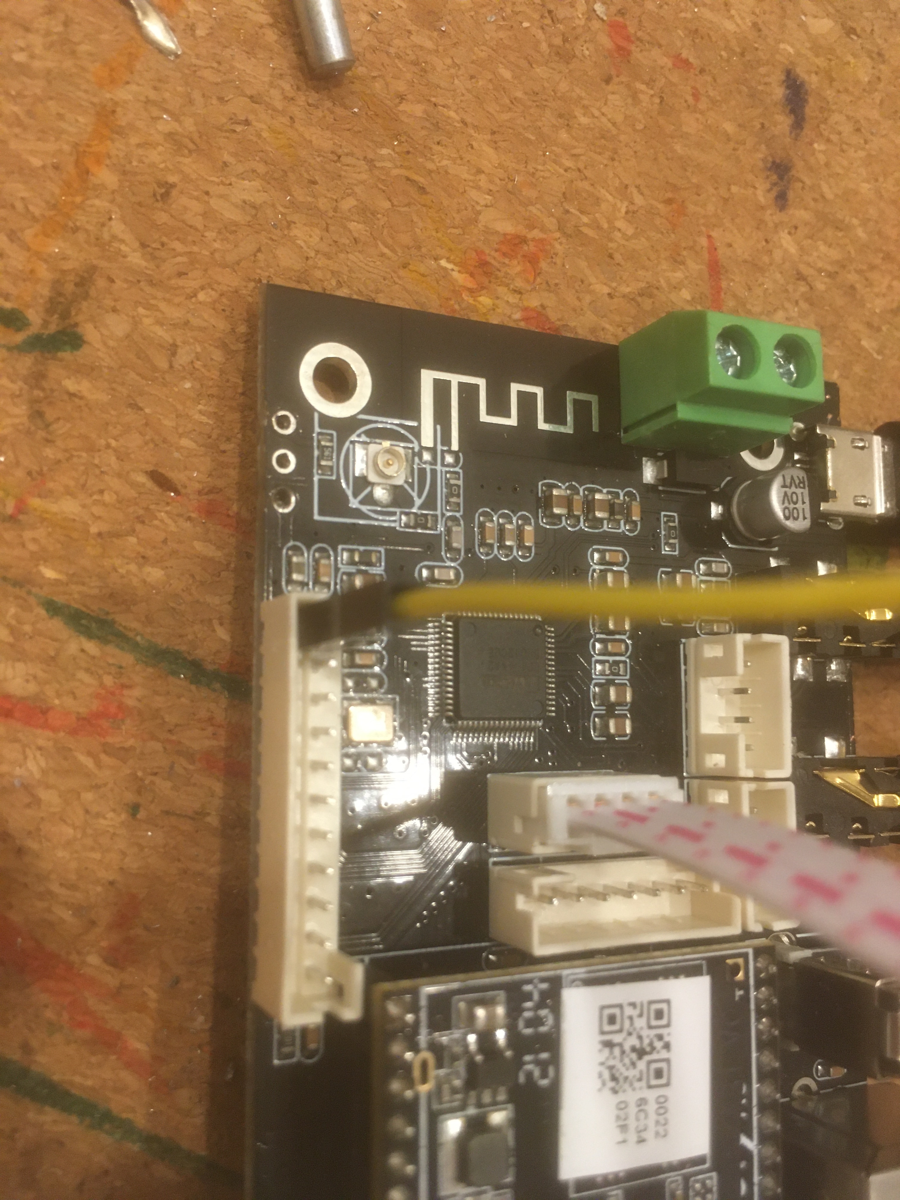
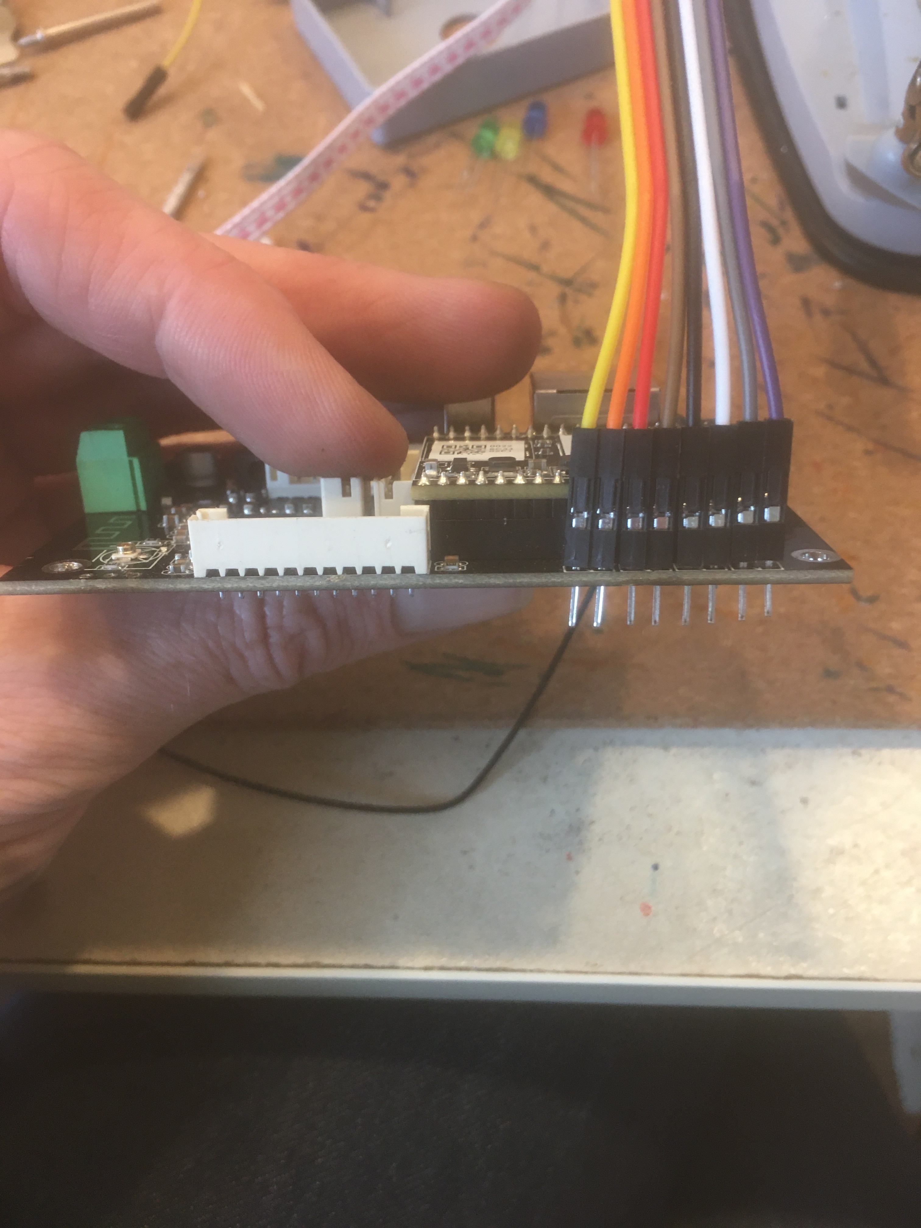
L’up2stream pro v3 est fourni avec une antenne wifi, j’ai récupéré une antenne bluetooth d’un ancien laptop que j’ai démonté et elle s’est très bien intégrée. J’avais pensé à les faire sortir de la boite mais mes tests m’ont montré que ce n’était pas nécessaire, en bluetooth ou wifi, la portée était suffisante pour mon usage et fonctionnait même derrière un gros mur.
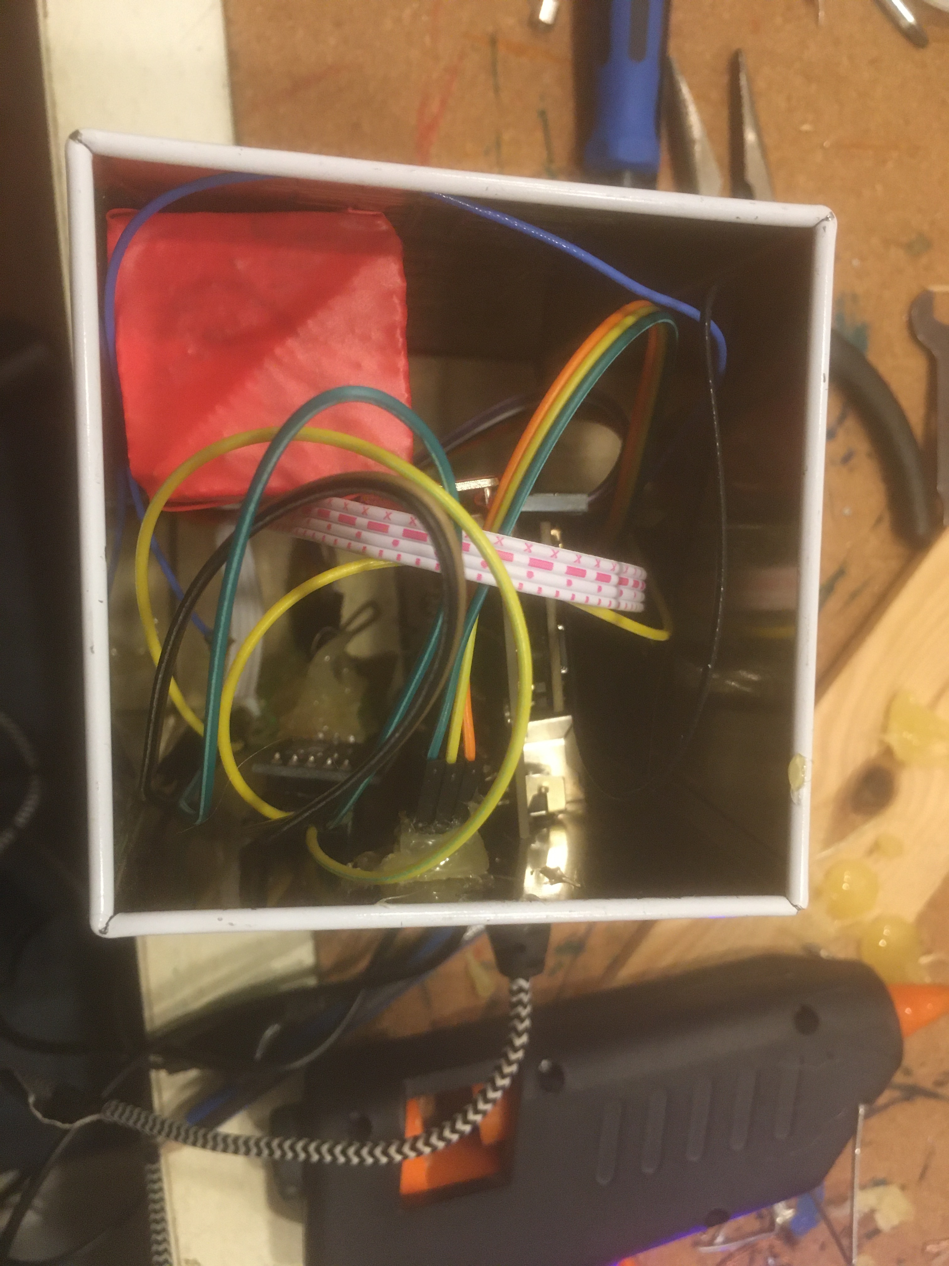
Il ne reste plus qu’à l’intégrer dans ma boite. Quelques découpes à la perceuse et à la dremmel, de la colle chaude et un système D pour maintenir le tout en place.
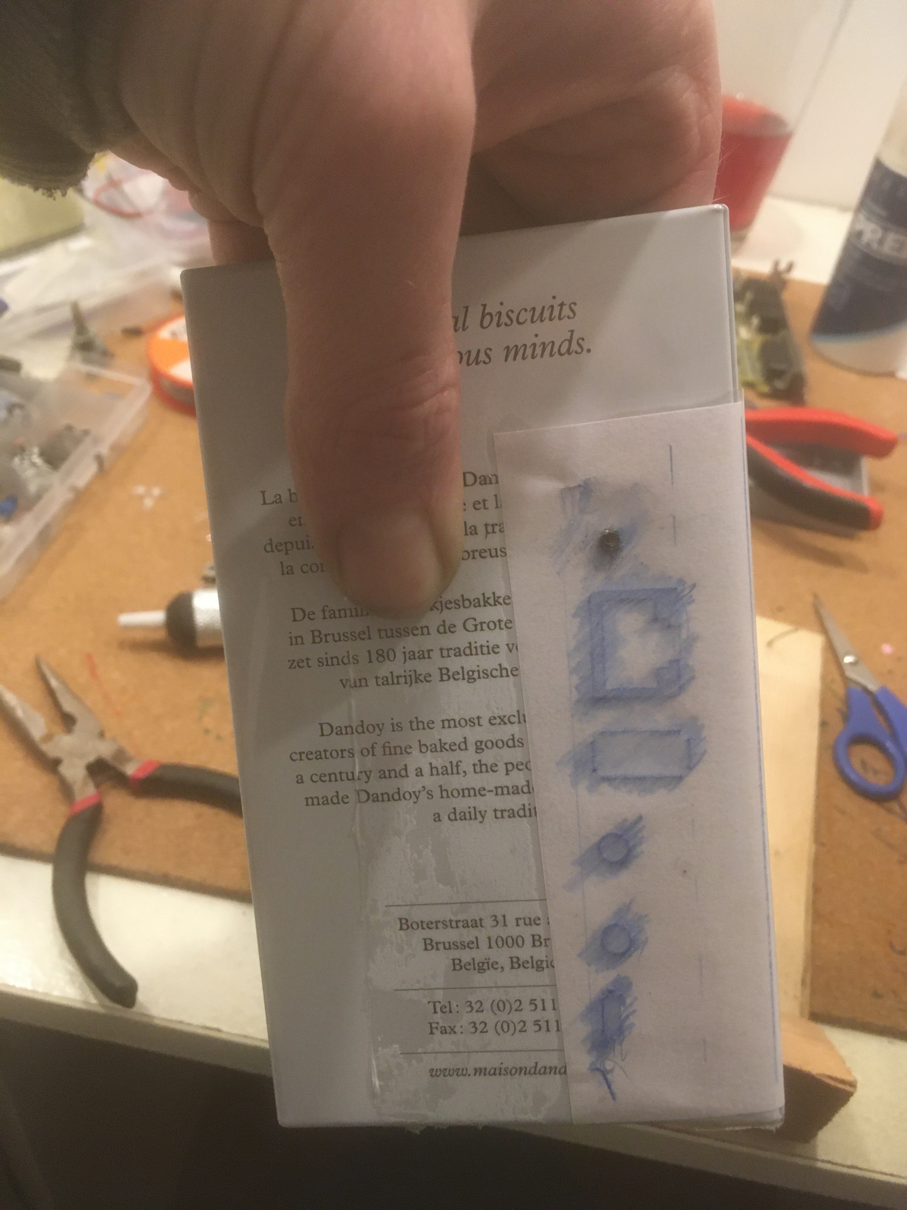
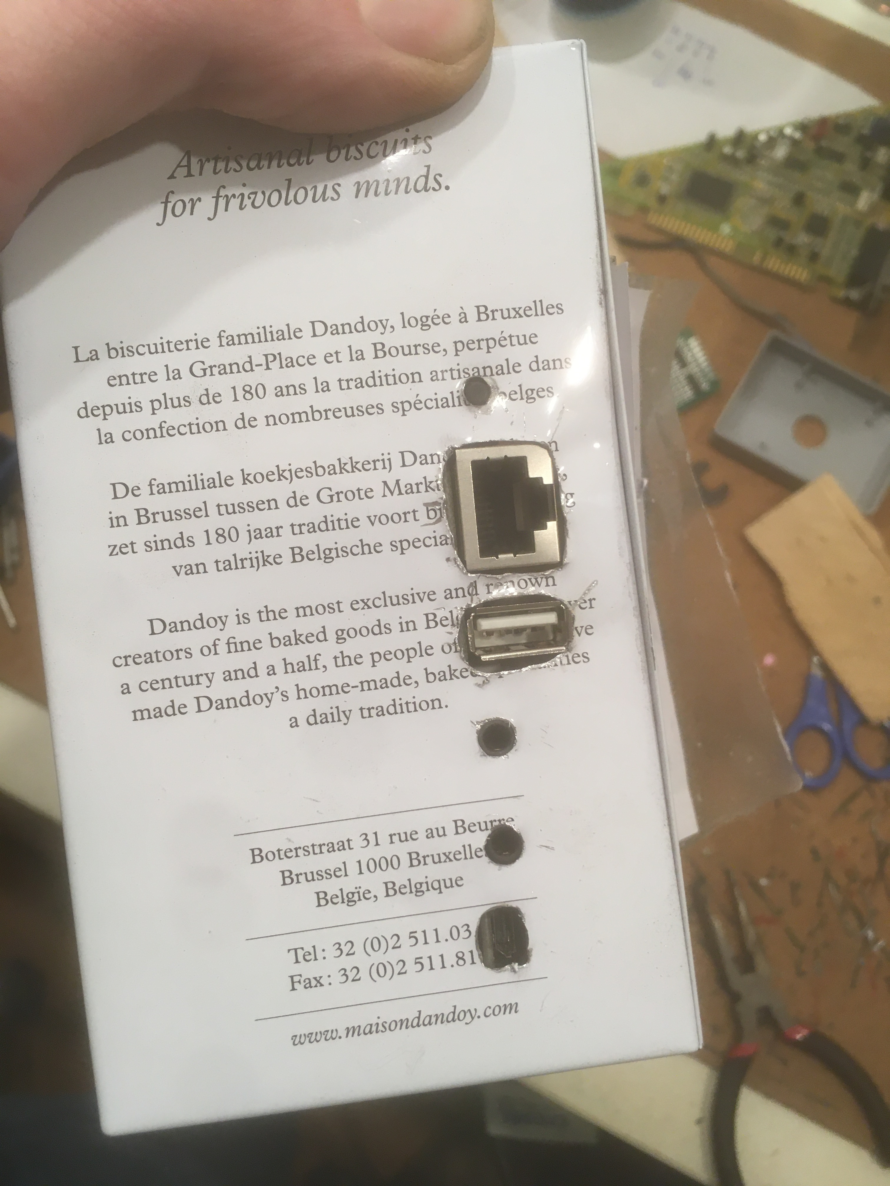
Et voici le résultat final : Une boite à biscuit Dandoy qui n’en est plus vraiment une.
Hi Everyone,
I have no specific training, I learn by myself by searching the internet and trying.
My first discovery with Arylic was a pleasant surprise. I was looking for a way to get started in multiroom but the existing solutions were too expensive (Sonos) and did not allow me to reuse devices that I already had in my possession.
As a first approach I bought the amp 2.1. I wanted to test the sound quality, the streaming stability… and I’m very happy with it.
I will soon integrate it into a project in order to “hide” the card in a beautiful box (I will let you know about this project when it is more advanced).
After this good experience I embarked on a creation with the up2stream pro v3.
The idea was to integrate it into a box of biscuits in order to have a decorative object that does not look like a multiroom receiver and which can be installed next to an amp or amplified speakers.
To be able to benefit from a maximum of the capabilities of the card despite it being locked in a box, I unsoldered the IR receiver in order to be able to deport it outside the box.
It was the first time I unsoldered a component from a board and it took me a while to be sure not to damage anything. I used a desoldering braid, a desoldering gun and a soldering iron. By alternating different techniques, little by little, I managed to remove the element. The holes were well emptied and simply by putting the receiver back in its housing, I could see that it was working perfectly and had not been damaged. I have a 30W soldering iron and I think it’s not enough to be able to desolder easily and quickly but with a lot of patience… it’s possible.
The second step was to deport the leds. The operation is a little more complicated and I was only able to remove one functional LED out of the four, but without damaging the card. Anyway I had planned other LEDs to replace them. After a little test, the soldering of my extension cables was done without any difficulty.
I wanted to add a volume button (although it’s not an amp and therefore the volume range is not very wide) which allows you to change modes at the touch of a button like for the amp 2.1. I had this button in stock, with five lugs. With a few tries I found the right combination by using the offset cable provided in the box and adding a cable. You have to be careful because depending on the connection, the direction of the volume may vary. I chose that the volume increases when turning clockwise.
The up2stream pro v3 is supplied with a wifi antenna, I recovered a bluetooth antenna from an old laptop that I disassembled and it integrated very well. I had thought of taking them out of the box but my tests showed me that it was not necessary, in bluetooth or wifi, the range was sufficient for my use and worked even behind a large wall.
All that remains is to integrate it into my box. A few cutouts with a drill and a dremmel, hot glue and a D system to hold everything in place.
And here is the end result: A Dandoy cookie box that isn’t really one anymore.