Table of Contents:
- Introduction
- Backstory? We don’t need no stinkin’ backstory…
- Failures in communication…
- A beacon of hope?
Intermission: WHY IS THIS POST SO LONG?! - The Savior of Sound!
- Pushing Plastic
- Next Steps
1. Introduction:
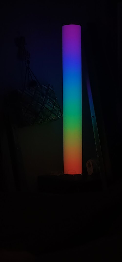
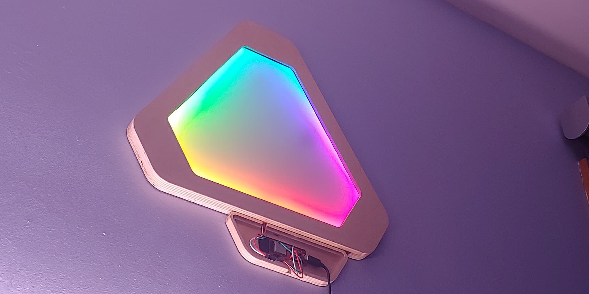
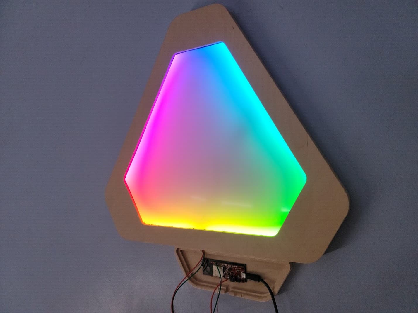
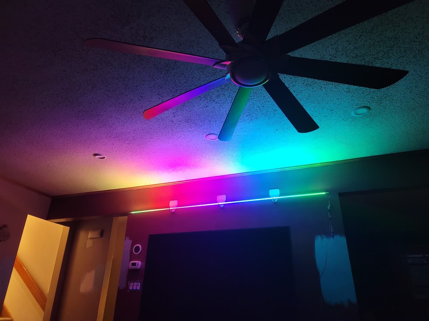
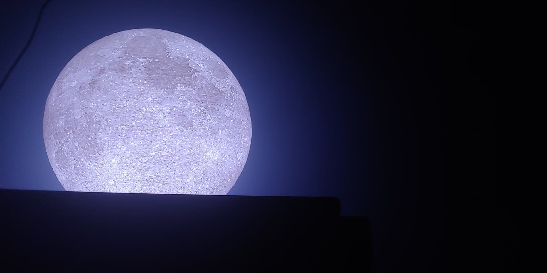
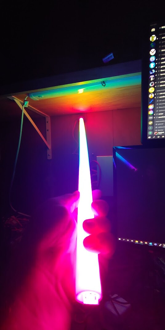
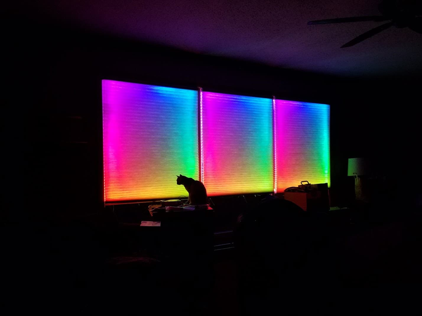
I am an adult on the autism spectrum. Audio and light are two of the ways I deal with stress. I’m also a senior IT systems engineer for a living. I work with technology day in and day out. I live and breath tech and love to DIY a lot of solutions. I have already sorted out the lighting for my day to day stress relief with a lot of RGBW lighting around the house, most of it homebrew using WLED and addressable LEDs. Enjoy photos of some of the things I’ve done with LEDs.
4’ tall floor lamp:
14" tall “Mega-leaf”
7’ of LED strip
3D printed Moon with addressable LEDs
WLEDsaber
Cat-mas lights.
2. Some backstory:
My wife and I purchased our Mid-Century Modern home (built ca 1959) in 2013 and I immediately launched into the process of automating the home while keeping the design aesthetics in place as much as possible.
One of the areas I’ve struggled with is a whole home audio system. Due to the layout of the home, there are four discrete levels to the home (split level design, everything is half a flight of stairs from everything else), and no clear path for a centralized audio system that makes home-runs to the various zones in each level. Not without cutting out a lot of plaster. Running cabling throughout the home to add Cat6a networking and 16/2 speaker wire was a four year process, and there are still holes in various locations that I have yet to close up.
3. Trials, Tribulations, and Ultimate Failures:
The end goal of the project:
- Centrally controlled whole home audio
- Home Automation Integration for notifications and control
- Good sound
- Good Wife Acceptance Factor
- Low frustration
The audio system started with some sad attempts at Raspberry Pi driven HiFiBerry or Pimoroni sound cards and DACs with homebrew software. This was… unreliable.
Connectivity was a pain, managing audio sources was difficult at best, and grouping zones sometimes resulted in the need to go physically unplug the power to a device to reset it.
Multiple different software solutions were attempted, and the random mishmash of speakers throughout the house with a Raspberry Pi stuck to it, either in a small case or the bare board was a bit disturbing and very unsightly. Wife Acceptance Factor was at an all-time low.
Remember what I said about being in IT? I don’t want to deal with the hassles at home that I have to at work. I’m entirely too old for it, and just want things to work.
Sonos was off the table due to price, Amazon Echo units had poor audio quality, and connecting the outputs to the speakers left me in the same situation as having a circuit board stuck to a speaker.
4. Craigslist to the rescue? Sort of…
Frustrated with the lack of progress, the functionality failure, and the constant battle with technology, I ripped it all out and went back to square one. This was around the time that the plaster cutting and wiring started in earnest.
In the basement on one end of our home is a mechanical room that contains the boiler, electrical panel, water main, water heater, etc. It also contains two equipment racks: a 12u full-depth server rack containing 240TB of Synology NAS goodness along with a Dell VRTX chassis with some pretty beefy server blades in it. The other rack above it is a 24u wall-mounted swing out network rack that contains the Unifi firewall, switches, and patch panels for the homeruns to the rest of the house.
How it started:
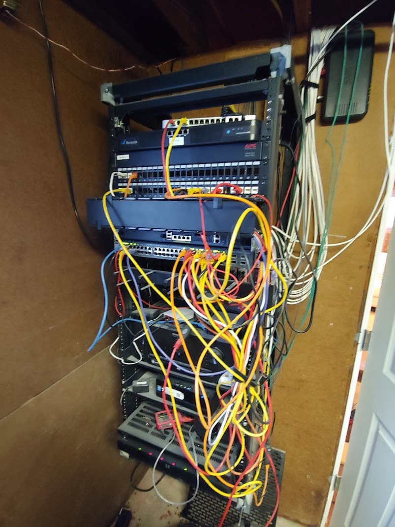
How it’s going:
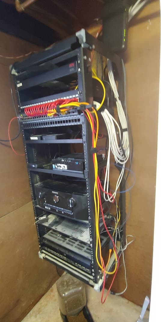
Getting wires from this rack in the bottom level of the home to the bedrooms on the top level on the far end involves running up through the wall in the main level above the basement, into the attic above that, down the entire length of the home through two separate attic spaces with a thin path between the two for wires, and then back down into the walls for each of the rooms. Worse yet, the ground level beneath the bedrooms is where the home office is located, and is arguably the most important place to run cables to for networking and the like. The cables have to run down through the bedroom level walls and into the ground level walls.
My amazing MSPaint skills here to show you the layout of the home.
Black boxes are floors, green line is ground level, orange box on bottom right is utility room where everything needs to come from. Orange box on top left and red line are future state, discussed further down this post. The red line also represents the approximate path that the wiring had to take to get from basement to bedrooms. Blue lines are representative of each audio zone. One line equals one zone.
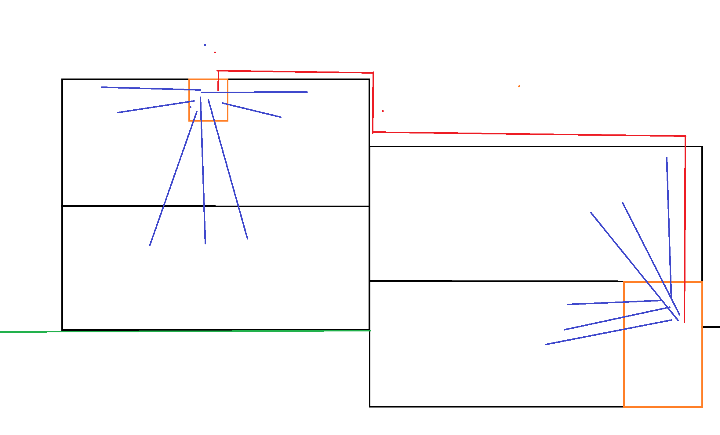
Now you see why it took four years.
While the Cat6a was being run, I also opted to run the 16/2 cable from the rack up to the attic spaces for each section of the house with plans to cut in some speakers at some point.
One night, while surfing Craigslist, I stumbled across a posting for a Russound 6 zone amplifier for a good price, as well as a bunch of new in box in-wall/ceiling speakers. I grabbed them and started the next step in my routine of self-punishment… Whole home audio that is integrated into the automation system.
I’ll make this short. The Russound amplifier can be controlled by proprietary in-room control panels in a wall switch box, or via serial. There is no in-between. Configuring a Pi or ESP8266 WiFi to serial bridge is beyond my skill set. A year of frustration led to the Russound being pulled from the rack in the basement and no whole home audio. I had given up on building a system myself, and was now eyeing Sonos…
Intermission:
I get it, I like to write long posts, and people have no attention span. Be patient, I’ll get to the point shortly (I lied, longly is more accurate).
5. In this corner, weighing in at 100 watts of pure unadulterated power…
Suddenly, a ray of light struck me from the heavens (a post I found somewhere online), and my passion and desire for completing this project was rekindled with a fury that will lead to my place in the annals of history.
Enter: Arylic Amp v4!
A Wi-Fi/Ethernet enabled audio board that can synchronize with others of its kind, has siblings that fit various other niches but offer the same strengths, and is priced reasonably well for someone who is averse to 400 bucks for a single speaker? YES PLEASE.
I ordered the Amp V4 and impatiently awaited its delivery.
When it arrived on my doorstep, I “squeeeeee’d” like a kid being handed a brand new puppy, and frantically cut the box open.

As I lifted the lid, a golden light shone forth and illuminated my face in it’s warmth and beauty.
I gently removed the Arylic Amp V4 from the box and placed it on my desk.

Connecting it to a set of enclosed ceiling speakers and connecting it to power, I promptly began the setup of the board with the ACPWorkbench tool.
The sound is amazing. As if the voice of my personal guardian angel were telling me that everything would be all right, they have my back through thick and thin.
I knew it then and there. This was the solution to my problem. This was my path out of the darkness.
6. Creativity at its finest.
My design plans for the whole home audio changed.
Things I had already done:
16/2 wire to all rooms of the house. Un-used as of yet.
Cat6a to all rooms of the house. 3+ cables per room (to support audio/video distribution/centralization).
The new design for the audio system still requires a centralized architecture, but it no longer needs to be centralized in one single location. Remember, the home has four floors arranged in a 2x2 structure. Two floors stacked on the left side, starting at ground level. Two floors stacked on the right side, halfway buried in the ground for the basement.
The right side of the house will have independent Arylic boards for each audio zone mounted in the 24u wall mount rack.
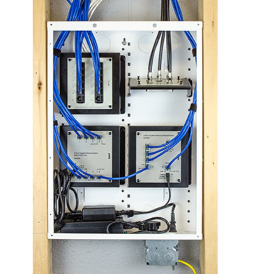
The left side of the house will have independent Arylic boards for each audio zone mounted in an in-wall structured media cabinet which will be mounted inside the central hall closet upstairs. This cabinet will be dedicated to the audio system, so it does not need to be very large. It just needs to have enough airspace and a vent to allow for air flow and cooling.
Something like this…
Power to the structured media cabinet will be provided by one of the 16/2 cables already run to this level from a 24v 500 watt power supply mounted in the basement rack. This cable will feed a small fusebox/distribution block. Additionally, there will be two Cat6A runs repurposed from the bedrooms and placed into this cabinet. One will be live, and the other spare. These are connected to a PoE switch in the basement. Unifi makes a small 5 port PoE powered gigabit switch that can run entirely off of the PoE uplink. This will provide network connectivity to the cabinet and the Arylic boards. The cabinet will provide audio to the bedrooms, bathrooms on these two levels, and the office and attached garage/workshop. The speaker wires running from the basement will be cut and redirected into this cabinet for these zones.
The rack in the basement will also have a separate 24v 500 watt power supply that will power the rack-mounted zones. Network connectivity is directly available here. This will provide audio to the basement rooms, the main living level, and the back yard patio.
Now I just need a way to mount these.
About two years ago, I picked up my first 3D printer and promptly started to teach myself Fusion 360. I now do some rapid prototyping for a few places using CNC, Laser, and Printing as a side hobby.
I started with the idea that I wanted to be able to clip the board into a housing and then hook it up. The housing needed to protect the board while providing ample air flow. This led to the need for different mounting solutions for the different scenarios: Rack vs Cabinet. The design evolved into a cartridge style mounting system that allows for quick and easy removal for service or upgrades, is tool-less except for the thumb screws holding the cartridge, and allows the board to be used as a tabletop amplifier device.
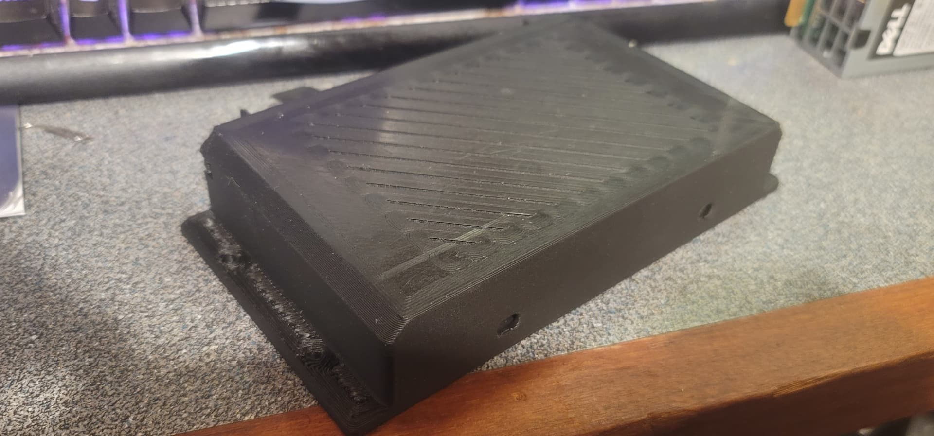
The design

The first print. Carbon fiber PLA+ prints so nice!
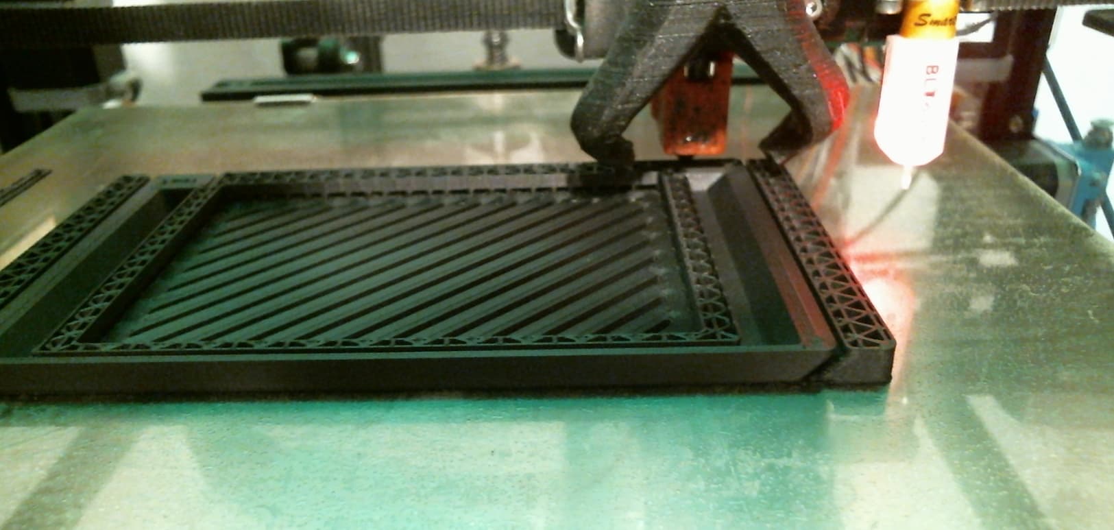
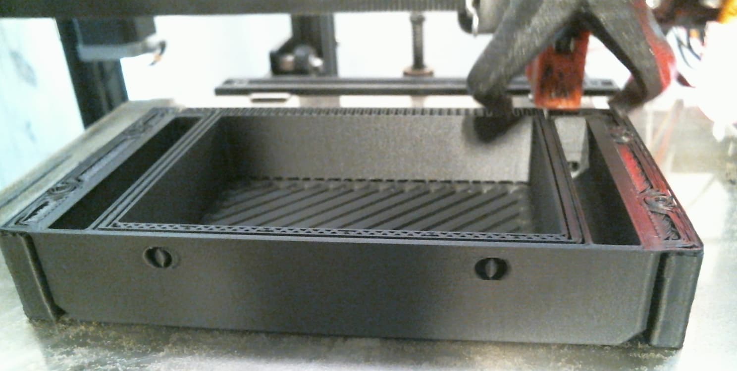
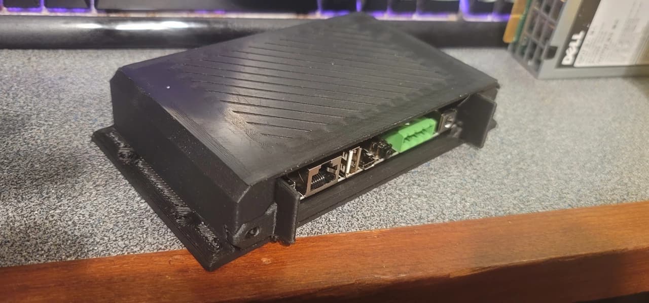
The board clips into the cartridge with no screws using the sides as spring locks and provides easy access to all ports front and back. It can be mounted in reverse in the cartridge so the ports can face either the back of the cartridge or the front, which is useful for rack-mount installs and exposing the status LED and IR receiver.
The rear clip that holds the board down in the cartridge.
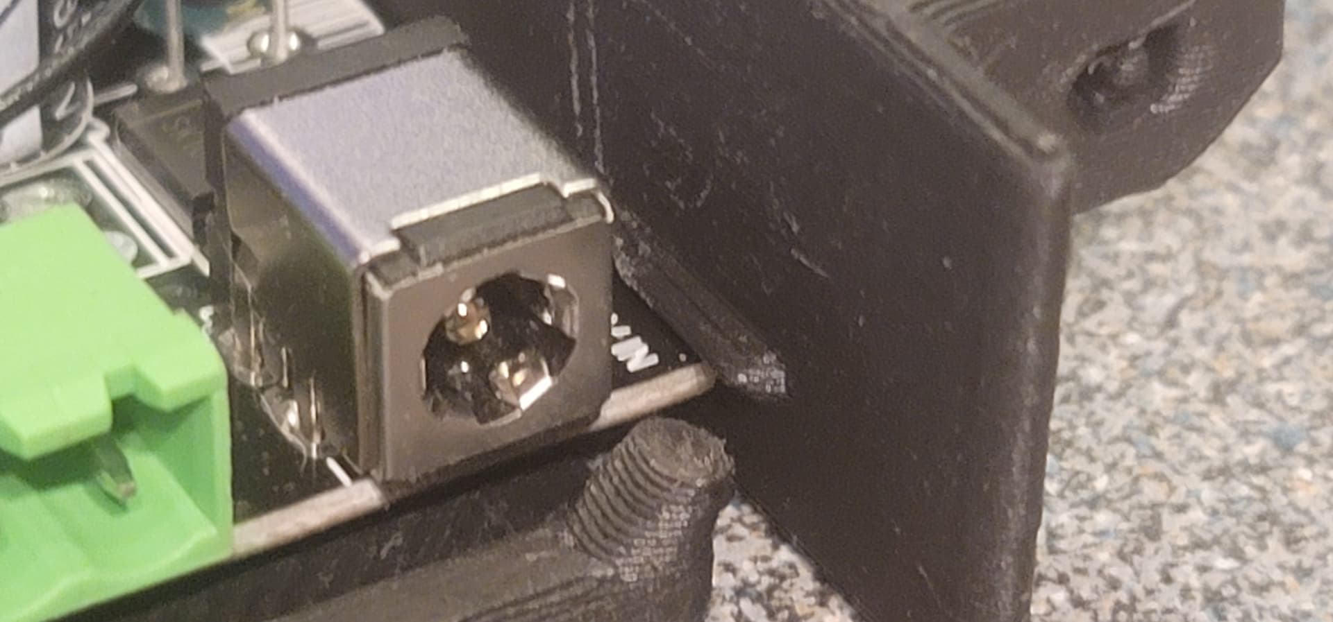
The front notch that the board slides into to hold the board down.
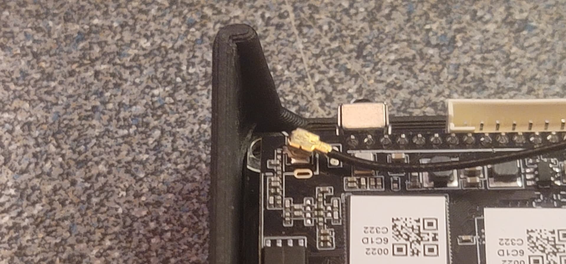
The cartridge, partially installed.
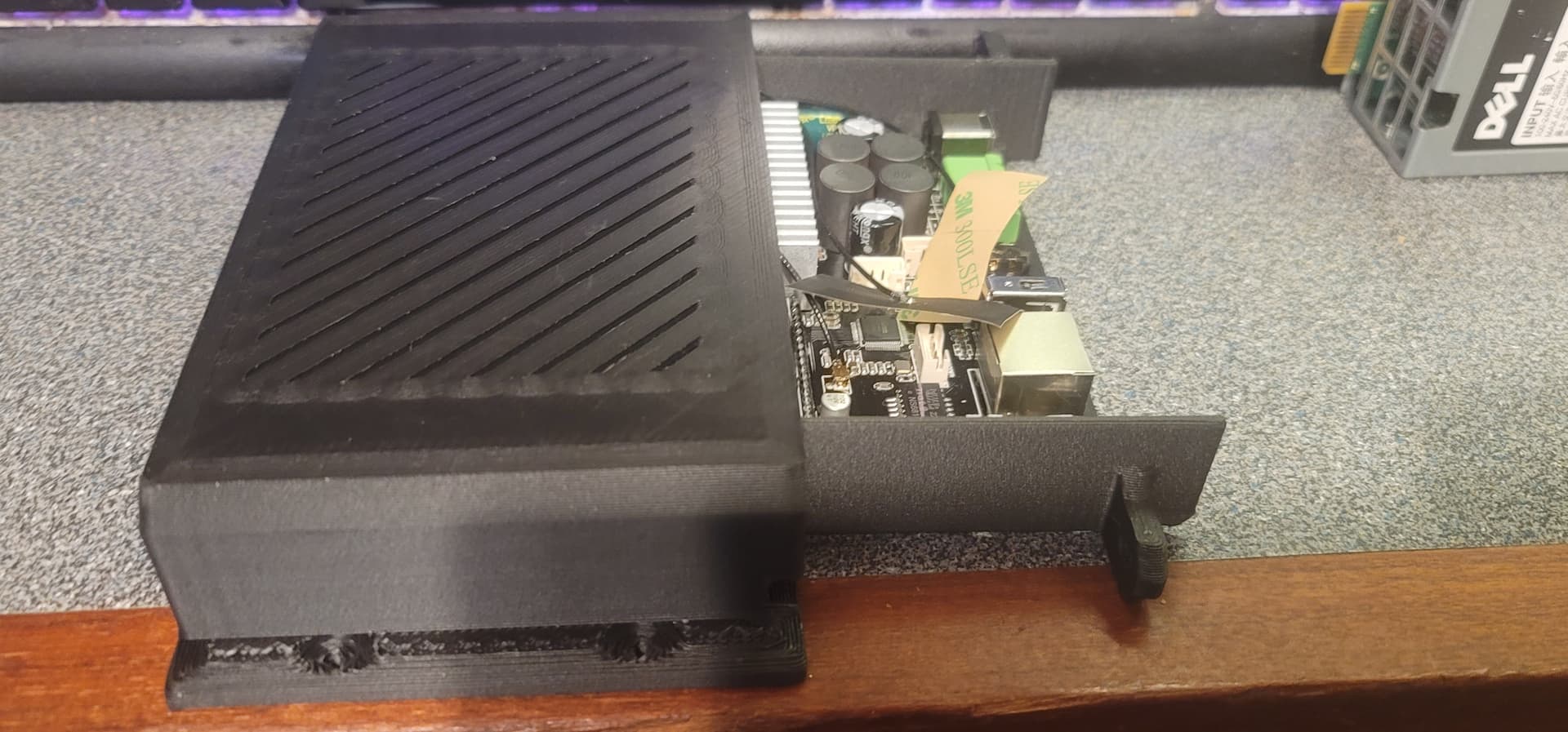
Front
Back
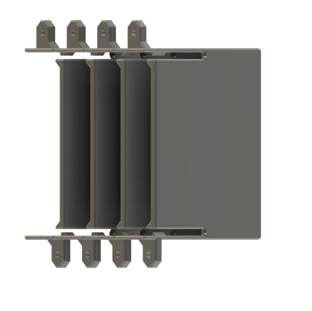
The cartridge slides into the mount/enclosure and thumb screws on either end of the cartridge face lock it into place. Cartridges are designed to be docked in close proximity to each other while not impacting air flow, which allows for a compact space-saving design. The cartridge and tabletop box designs are complete, and no further design revisions are on the horizon for them at this time.
2U layout (room for ~8 devices in this config, possibility for 10 in my measurements)
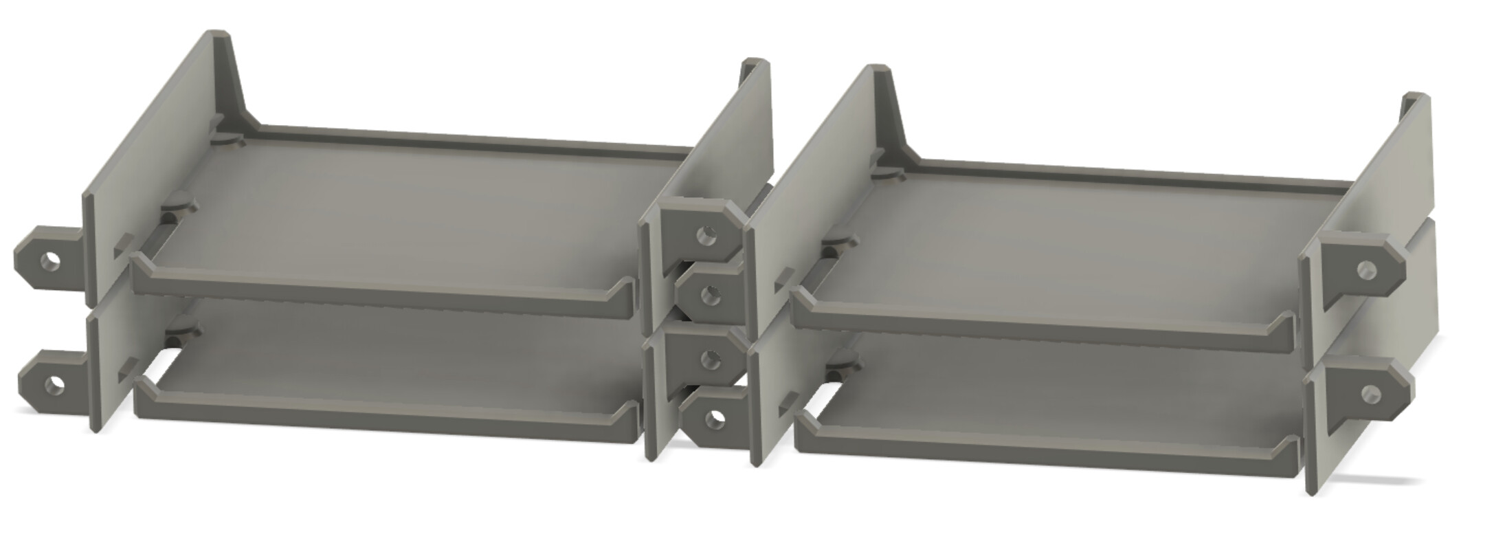
4U and media cabinet layout
The rack mount is still in progress and will be available as a 2u and 4u unit allowing for extremely high-density many-zone installs. No pictures of that one yet, as the design is in flux.
The cabinet mount is also still in progress, but will have the rack mounting flanges located on the back of the module to allow surface mounting the enclosure, and will also be equipped for DIN rail mounting.
7. The future, as the budget allows…
Arylic, I’m not one to ask for handouts, but I wouldn’t say no to a sponsorship from you for a stack of Amp V4 boards. ![]()
The wife likes the one zone I have, but due to some outstanding medical bills from my time in the hospital with COVID, I am now on a budgetary hold. Sneaking this one purchase past her did not result in my death, but the next one definitely will. A court would acquit her of all wrongdoing.
All joking aside, I have a total of ten zones in the home that I’ve already strung cabling for, and as soon as the bills are covered (2 more years or so) or I win the lottery (realistically, never), I’m planning to finish out the audio system. I already have all of the speakers from that Craigslist score, I just need the boards now. I’ll print cartridges out as I go and slap a board in it whenever I can buy another.
Anyway… Sorry for the long post. Thoughts get stuck in my head, and writing is one of the ways I get them out.
All designs will be released publicly once I am finished with them.