I connected the GPIO1 pin of the board to a relay module, along with 3V and GND from the 4pin GPIO header.
I configured the pin as OUT CTRL via ACP Workbench.
Now I see the relay switching when the music starts, but it acts the opposite way.
When I turn on the board the relay is triggered immediately and closed the circuit, without any music.
When the music starts, the relay is triggered again but it opens the circuit returning to a stand-by position.
When the music stops (after a while), the relay closes again.
So, if I connect the amplifier power through the NO connection of the relay, the amplifier is on when there is no music and off when the music is playing.
If I connect the amplifier through the NC, it acts the correct way when the board is powered on, but when the board is off the amplifier is powered on with no reason.
Ok, that’s what I understood too.
So, how can I connect it to a relay module in order to close a circuit, so I can power on the amplifier?
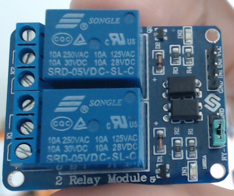
I have this kind of relay module:
The output level of PROV3 GPIO is 3.3V, so you need to check if the relay accept this voltage. Anyway, if you have module on hand, you could give it a try, connect the VCC/GND/IN1 to VCC/GND/GPIO of PROV3, and the test the connectivity of the relay output. I think you should be able to select the correct logic to control the power.
I found the problem was the relay module itself, because it is a low level trigger and it’s not configurable (by the way, that relay needs 5V, but it also worked with 3.3).
Now I took a new relay module (3.3V), which works with high level and it works correctly.
Hi,
Please help me, how did you saved the GPIO setting, becose for me it’s working till the board is connected to the computer, but after a reboot not. I saved the settings, but as it seems didn’t happened. I use ACPWorkbench 2.33.0)
Thank you