For a special project, I need to connect an Up2Stream Mini to a Raspberry Pi.
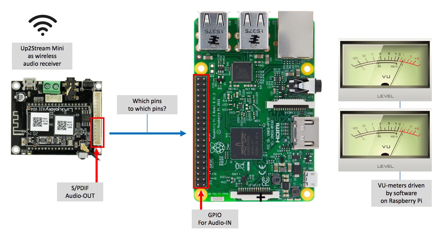
What I am building (see picture below)
The Up2Stream Mini is used as wireless audio receiver.
The Mini’s audio output will have to be sent to the Raspberry Pi.
The Pi processes the incoming audio signal, to drive visual VU-meters on a display (with software installed on the Pi).
My questions
The Raspberry Pi does not have a standard connector for Audio-IN. But I understood it is able to handle S/PDIF via the 40-pin GPIO connector.
Is it possible to connect the S/PDIF connector of the Mini, directly to the GPIO pins of the Raspberry Pi?
If so, which pins of the Mini should be connected to which pins of the Raspberry GPIO header?
Hi Ernst,
Not really my forte, I don’t think you can input S/PDIF without a pi hat, but you can definitely input I2C (2 wire digital protocol)
Not sure if this helps?
You must be dead keen on achieving your peppymeter thingy
Cheers,
Steve
I think you are right that a HAT board for the Pi is needed. Reading the info (here) about the ‘HifiBerry Digi+ I/O’ you mentioned, it says:
HiFiBerry Digi is a high-quality S/PDIF card for the Raspberry Pi. It uses the I2S sound port that connects directly to the CPU without the need for an additional USB conversion. It does not only feature an output (optical and electrical), but also inputs (both optical and electrical).
So from this I think the HifiBerry Digi+ I/O board:
Adds S/PDIF to the Raspberry.
Has electrical and optical input.
My questions:
(To you Steve and anyone else who can help me understand)
Is it correct that I need a board like the HifiBerry Digi+ I/O?
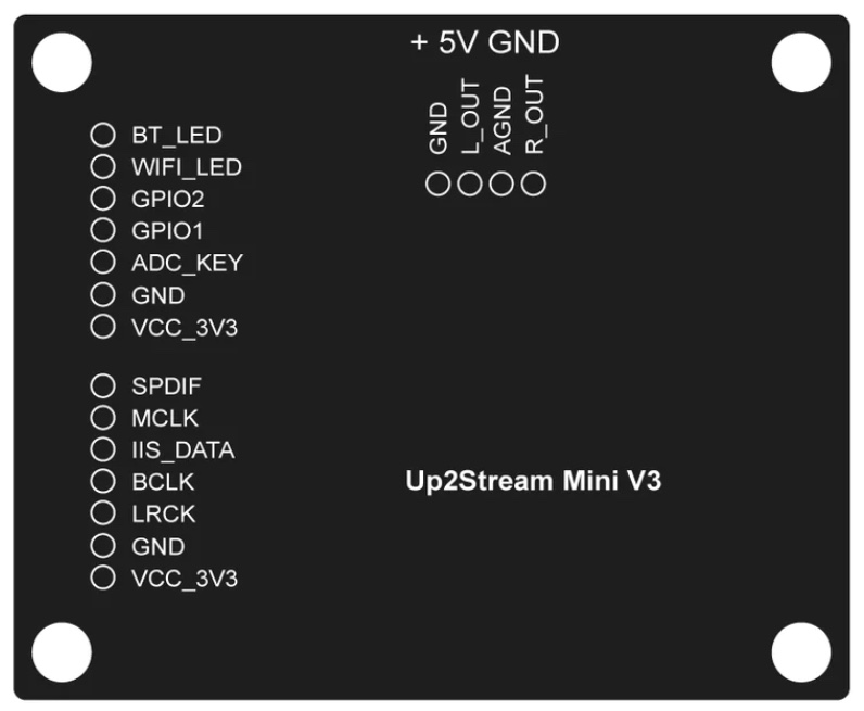
How can I physically connect the Up2Stream Mini to the HifiBerry board? (The Up2Stream Mini has a 7-pin S/PDIF connector. Where/how does this connect to the HifiBerry board)?
Hi Ernst,
More than happy to help (in a small way)
Someone more Pi knowledgeable than I might be able to tell you if a I2C connection is possible, to avoid buying a hat.
To answer your questions:
Q1. Yes I think you would need a hat for the S/PDIF.
Q2. You would use 2 wires on your 7 pin connector, the S/PDIF and the GND pin. Fit a RCA plug for the connection to the hat ( centre pin digital signal of course)
To quote from the SOC documentation (Raspberry Pi’s system-on-chip):
The PCM audio interface has 4 interface signals;
PCM_CLK - bit clock.
PCM_FS - frame sync signal.
PCM_DIN - serial data input.
PCM_DOUT - serial data output.
Based on that information and the GPIO 40 pin header documentation, I presume the following connections are logical:
GPIO - Signal, comment 18 - PCM_CLK, connect to BCLK on Up2Stream 19 - PCM_FS, connect to LRCLK 20 - PCM_DIN, connect to IIS_DATA 21 - PCM_DOUT, not used
I’m interested in your usage case so please let us know how it works. Good luck.
Please note: The RPi GPIO numbers listed above are “Broadcom GPIO numbers” and NOT the pin number on the connector 40-pin connector. You can look up the connector pin numbers here.
Yes. Those are the correct pin assignments for a connection providing I2S data into the Raspberry Pi.
Yes. The fourth I2S interface signal is MCLK but is only necessary when the connected device does not have its own local oscillator/PLL. In this case the RPi has its own PLL.
My original post only addressed the logical connection. Since we are now discussing the physical interface - pin numbers - we need to also consider the electrical interface. Specifically, we need to know the signal levels output from the Up2Stream Mini. @Steve1 provided a picture of the board showing the signal names on the 7-pin connector having the I2S signals. Since VCC_3V3 is including in this interface my assumption is the electrical voltage swing of the I2S signals are 0 - 3.3V which would be compatible with RPi. However, I’m looking at the backside of my Up2Stream Pro V3 and the power pin is marked VCC_5V. I did not find a specification for this interface in the user’s manual. Hopefully someone on this forum can confirm what the correct voltage signal levels are on the I2S interface. My advice is to not connect until you can get confirmation.
The I2S spec is saying the signal conform to (more or less) legacy TTL voltage levels. Those can be met with either CMOS drivers powered either by 3.3V or 5.0V supply. The RPi can not accept a signal level that swings above 3.3 + 0.33V.
So I can only assume the Up2Stream is driving 5V levels given the supply is at 5V. Can you probe a signal such as the LRCLK which I think should be about a 50% duty cycle. If you DVM reads 1.6V then we know the voltage swing is 0 - 3.3V. If it reads 2.5V it’s a 5V swing.