I am new to Arylic and I have just placed an order for the Up2Stream AMP v4 (plus remote control). I have searched and review many of the posts here and managed to pick up some very good information here and there (Many Thanks to @EthanEsrah, @ker, etc). I also recall some mentioning the lack of technical information especially on the IO ports - in relation to the default software setting. Someone was also trying to put together a table of voltage trigger values for the different functions (by trial and error). This is surprising to me.
What I wanted to find out more was on the Volume header (item 12. PH2.0-4P: GPIO2, GPIO1, GND, VCC3V3) and how a normal rotary encoder (eg Bourns PEC11R) could be used to vary the volume. Are the coding resistors already built on-board (the Up2Stream AMP v4) wired to the header ? Based on what I could see on the Volume Knob expansion board, there are no visible resistors or capacitors on it.
I would really appreciate it if someone could share some of these details with me. It would certainly be most useful when I start to work on the board when it arrives.
Hi Yeow,
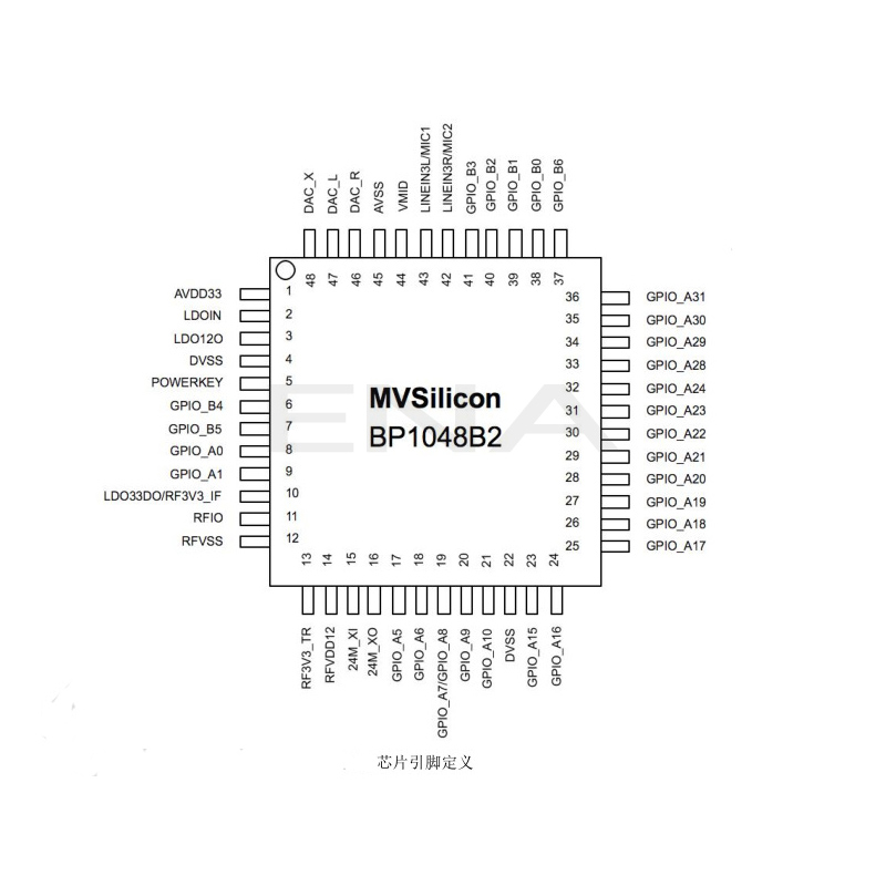
I’m not sure if this assists you but looking a a Pro board that I have on my bench the GPIO 1 & 2 on connector J12 appear to be directly connected to the MVSilicon BP1064A2 IC. Pin 3 of the connector (GPIO_1) goes to pin 35 of the IC and pin 4 (GPIO_2) goes to pin 34 of the IC.
I haven’t been able to find out much about the IC only that it is a BT5.0 dual-mode 32-bit DSP audio processing controller and it appears to perform a multitude of functions, pin 34 of the IC is labeled GPIO_A17 and pin 35 GPIO_A18.
My assumption is that the IC performs stepped attenuation of the gain via the encoder.
Steve
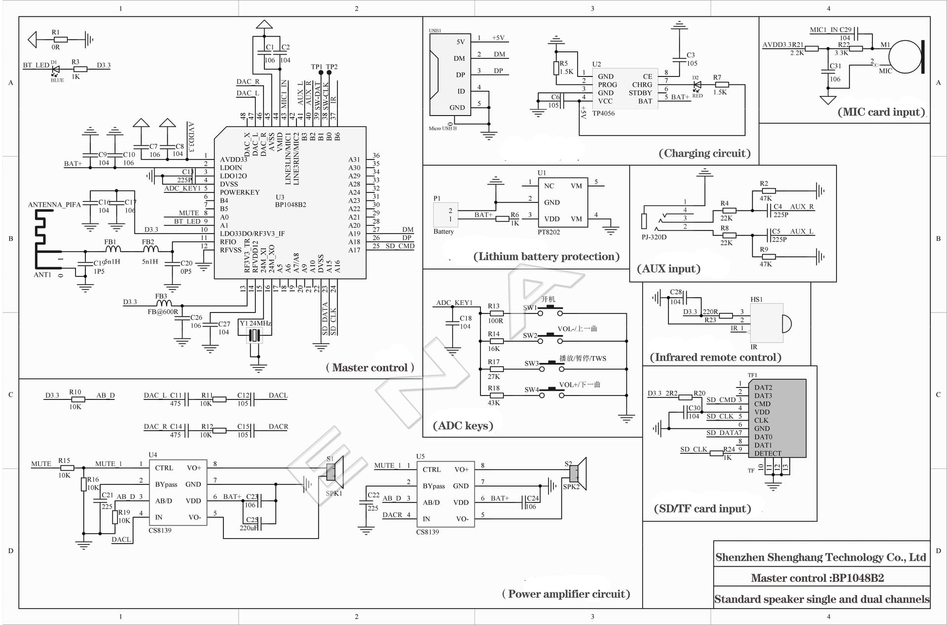
Thanks for checking it out. I did some trolling around for more info (datasheet) on the MVSillicon BP1048B2 and its quite lacking. I am attaching 2 files that provided a little more info.
Yes, I assumed the same about the encoder and the chip. So unless we know how they programmed the chip for those 2 IO pins, we really do not know what trigger values would be within the program range. In one of the attached files, there are some circuit info and you can see, the ADC_Key1 resistor values differ from that which are recommended in the Arylic product manual ie. Vol+ : 43k, Vol- : 16k vs Vol+ : 5.6k Vol- : 8.2k (Arylic manual).
Looks like I have quite a bit of work to do when I get my hands on the board… . Thanks again !
I am doing an update here for the Up2Stream AMP V4 and the Volume header wired with a BOURNS PEC11R-4220F-N0024 encoder. The wiring is as follows :
Connector type PH2.0-4P (4-pin male) on the Up2Stream AMP V4 board.
Pin 1 (GPIO2) -----> A Channel (on Encoder)
Pin 2 (GPIO1) -----> B Channel (on Encoder)
Pin 3 (GND) -----> C Common (on Encoder)
Pin 4 (VCC3V) ----- not connected
With the above, turning the encoder anti-clockwise would Reduce the volume and clockwise would Increase the volume.
Credit and Thanks to Frank Zhang (zpl1025) for his expert knowledge shared with me !