I am currently working on transforming two old passive speakers to wireless streaming active speakers.
For this purpose I will use the Up2Stream Amp v4. And to power the Amp v4, I would like to use a 2-wire-cable with a JST socket.
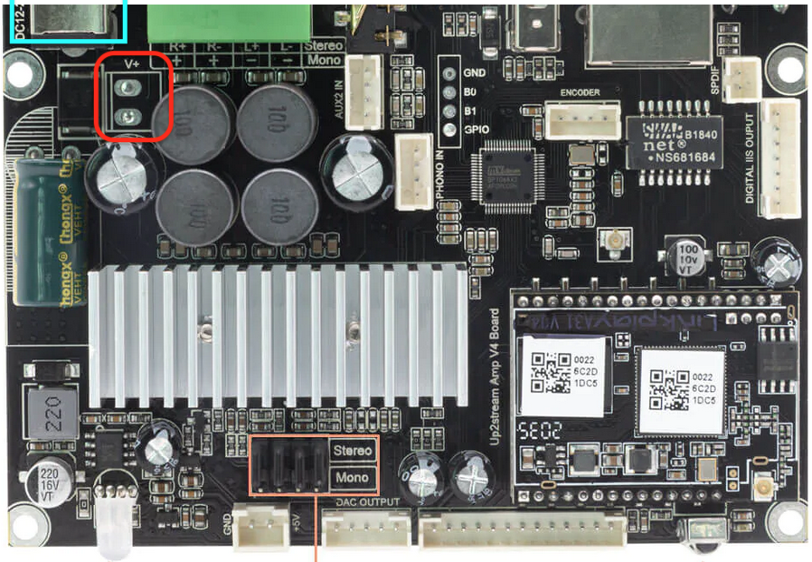
On the board I have seen a spot with two holes without a connector, marked as V+ and GND (see Red box in picture). This spot is near the DC input connector (see light blue box in picture).
Question:
Can the spot in the red box be used to connect 12v DC input to?
(If so, I would like to solder a 2-pin connector to it)
Hi Ernst,
Pretty much all solder used these days is lead free and the melting temperature is higher. In such cases I usually try to reflow the join with some 60/40 resin core solder (40% lead) this can often make it flow enough to either suck with a solder sucker or wick.
Alternatives might be to either get a small drill bit and drill through the solder pad or solder your DC in wires directly to the board.
Have fun!