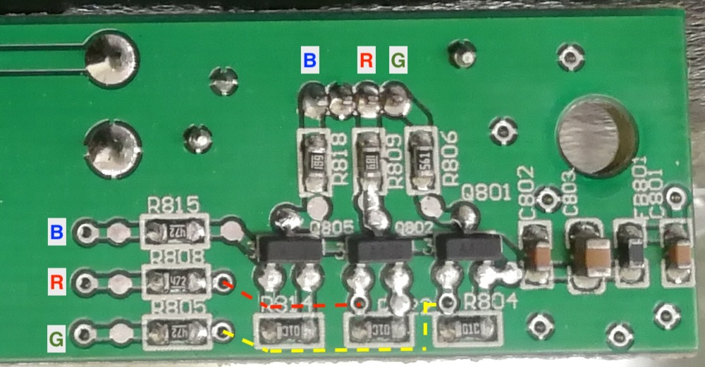
I’m hacking the original RGB LED in a soundbar. It was also used to indicate input source with the original circuit board (CB) using 3 PNP transistors, 1 for each LED colour, driving a common cathode LED and thus an ideal solution.
Is using the 3 PNP setup a good, bad, or indifferent idea with the Amp2.1?
Is the 1K resistor for each colour listed in the Amp2.1 manual meant to protect the LED or the amp? Following the specs for the LED I’m using, the resistor values should be much low than is suggested.
If I continue to use the PNP transistors in the circuit, are the 1K resistor still relevant?
This LED is capable of RGB=W as I tested it on my breadboard with a diode to each of the 3 RGB pins to prevent unwanted LEDs from illuminating. Can one of the Amp2.1 LED pins be used to safely drive all 3 colours? Is that with or without PNPs?
The AMP2.1 LED PINs are using common positive connection, it’s pull down to GND to turn on the LED, and open to turn off. It’s different with this board.
This CB is using PNP with common cathode LED. So the AMP2.1 can also work as I have already confirmed. It’s the questions I listed that I’m uncertain about.
ok, the PINs on AMP2.1 is used to drive the LED directly, so the resistors are used to limit the current. And when connect to this PCB, it’s only used as driving signal, I think it’s fine. And it’s a LED circuit, won’t do any damage, so just try it
And regarding question 4, it should not work. You could twist all 3 PINs together to show white color, but then you can’t control each color separately.
I was able to illuminate the tricolour LED, each individual RGB colour, without resistors via the onboard PNPs
I was able to illuminate the tricolour LED as WHT, by driving all 3 RGB PNPs after adding a diode from–in my case the USB signal–to each. Although it may be overkill, I also added 3 more diodes to prevent the amp from receiving the signal going to the 3 PNPs
I did not use the 1K resistors on each of the R, G, or B LEDs in the manual’s diagram