Hi everybody,
for those of you, who like to use the I2S capabilities of the boards and do not have any clue how to do it. this is for you.
In this manual I’m using three different clients.
The first one is a simple, tiny and very cheap Dac with the PCM5102 chip that will make the sound quality much better. I still recommend to use the Arylic DAC extension board, because I personally think it sounds better. But, that’s up to you.
The second one is the Wondom ADAU1701 Dsp board. It’s a Dsp that can be programmed with Sigma Studio software. It has 2 analog inputs, 4 stereo I2S inputs, 4 analog outputs and 4 stereo I2S outputs.
The third one is the Wondom JAB5 Dsp Amplifier board. It has two analog inputs, one I2S stereo input, one bluetooth 5.0 Aptx-HD input, 4 x 100W amplified outputs and one stereo I2S output. The amplified outputs can be bridged so you can use them to make a 2.2/2.1/2.0 + I2S system.
Note this is an Arylic forum and I only discuss how to connect the Up2stream boards to the Wondom boards and how to set the settings in Sigma Studio. I assume that you know how to programm them and make a filter chain. There are lots of tutorials and videos in the internet on how to do that.
I’m not a guru on I2S and have not much experience. So, if I’m wrong on something, than please let me know.
First:
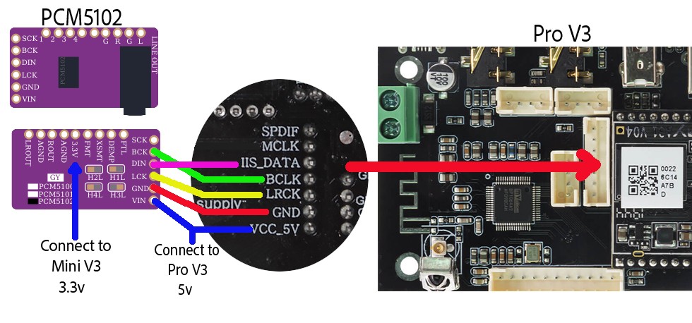
Connect the Pro v3 or Mini v3 to the PCM5102. Masterclock is not required (MCLK/SCK).
GND - GND
LRCK - LCK
BCLK - BCK
IIS_DATA- DIN
For powering the PCM5102 from the Pro v3.
VCC_5V - VIN
For powering the PCM5102 from the Mini v3.
VCC_3V3 - 3.3V
That’s all. See picture:
Second:
This is how to connect to the Wondom ADAU1701 Dsp board and chain it to the PCM5102. The PCM5102 in not neccesery if only Analog output is used.
Masterclock is required (MCLK). Power (VCC) leaves unconnected.
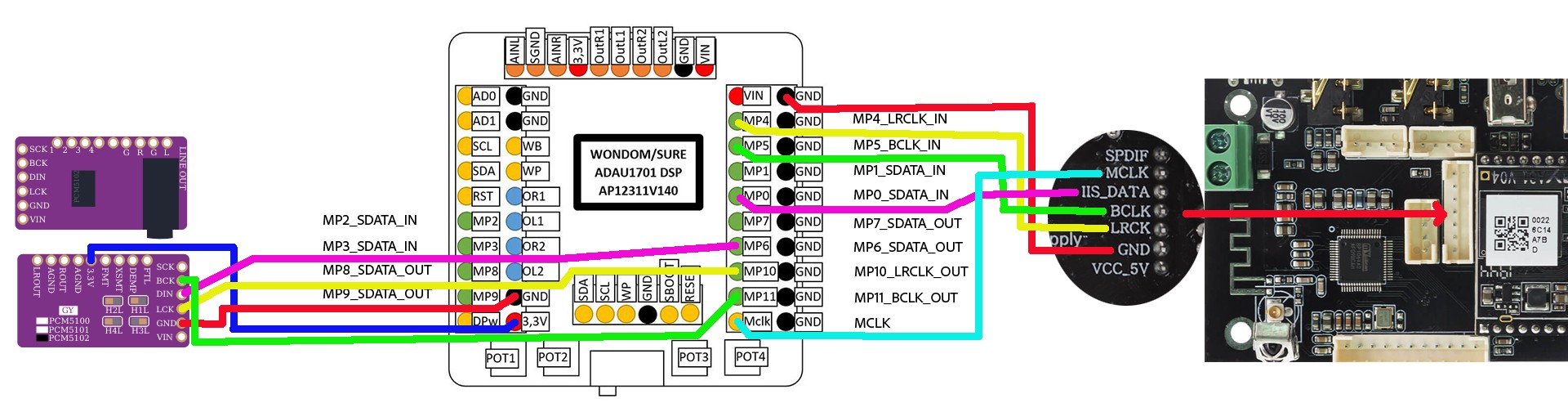
Pro v3/Mini v3 to ADAU1701:
MCLK - Mclk
GND - GND
LRCK - MP4
BCLK - MP5
IIS_DATA- MP0
ADAU1701 to PCM5102 (Masterclock is not required (MCLK/SCK):
MP11 - BCK
MP10 - LCK
MP6 - DIN
GND - GND
3,3V - 3.3V
See picture:
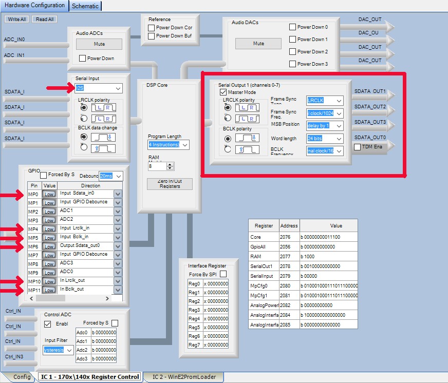
Create a new project in Sigma Studio or edit an existing one. Be sure you change the settings as in the following picture.
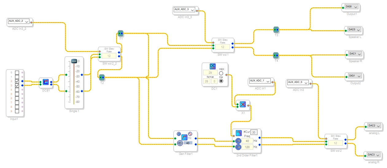
In the schematic input 0 and 1 is analog, 2 and 3 is I2S. Output DAC0,1,2 and 3 is analog and DIG0 and DIG1 is I2S. An example is in the next picture.
Third:
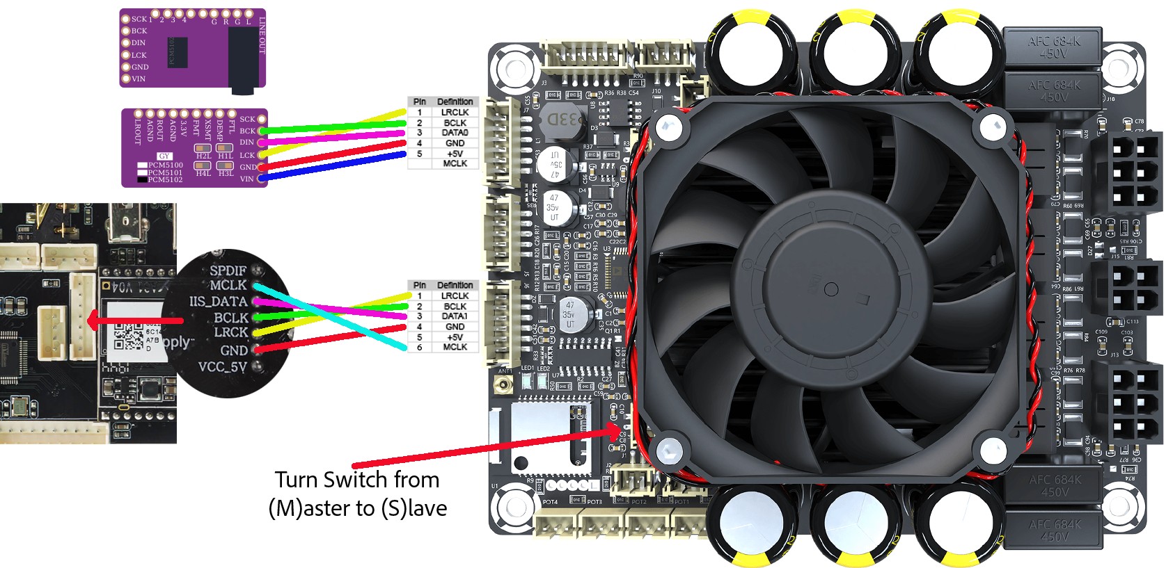
This is how to connect to the Wondom JAB5 Dsp Amplifier board and chain it to the PCM5102. The PCM5102 in not neccesery if only Analog output is used.The JAB5 Bluetooth and I2S input can not be used at the same time. So, it’s necessary to turn the onboard switch from (M)aster to (S)lave.
Masterclock is required (MCLK). Power (VCC) leaves unconnected.
Pro v3/Mini v3 to JAB5:
MCLK - MCLK
GND - GND
LRCK - LRCK
BCLK - BCLK
IIS_DATA- DATA1
JAB5 to PCM5102 (Masterclock is not required (MCLK/SCK):
BCLK - BCK
LRCK - LCK
DATA0 - DIN
GND - GND
3,3V - 3.3V
See the next Picture:
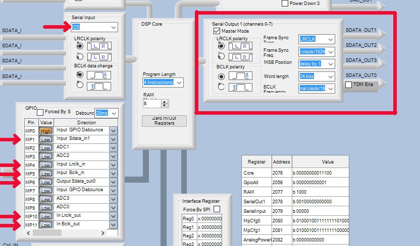
Programing in Sigma Studio is just slightly different from the Dsp-only Board. DATA input is MP1. See next picture. The input for I2S in the schematic is the same as for bluetooth and that is 4 and 5.
That’s it.
Sidenotes:
There are a few downsides on using I2S. On the Up2stream boards the internal Dsp functions and volume controle of the remote are dissabled when in multiroom mode. In the app its still working though.
The other is not related to I2S. In multiroom mode the clients are in mixed stereo. That means you here the same on both channels.
Hope this all helps.