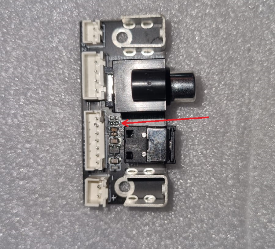
I accidentally tightened a screw right through my casing and into my SPDIF input board.
It ended up damaging a discrete smd component. Looks like a capacitor to me. The arrow in the picture points toward the pads where it used to be.
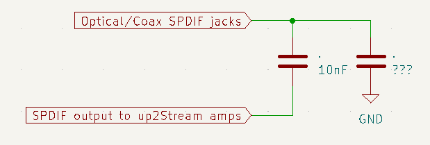
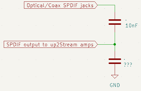
Circuit-wise it sits between ground and the SPDIF output pins that go to up2stream amps. Next to it is a 10nF cap that is inline with the SPDIF line from optical/coax jack and the SPDIF output pin. See schematic
And it got me thinking, because I want to connect it to the U2S HD DAC, do I even need any signal conditioning. It seems the U2S HD DAC has some caps and resistors at the JST connector which appear to be absent from other boards.
Hi Brett,
With the HD board you probably just need to connect your digital IN to the correct pins on the JST connector and configure SPDIF IN with the ACP Workbench tuning tool.