Searching for: Volume control button that connects with Arylic Up2Stream

Good Progress Today and I have a made a working solution using “httpapi” with Next & Previous Tracks

  • Testing with a Arylic Mini
  • Music Source Playlist on Synology NAS Drive

A Very Rough Video

A Log File

18:11:03.226 -> BUTTON_RIGHT
18:11:03.601 -> HTTP Response code: 200
18:11:09.603 -> BUTTON_RIGHT
18:11:09.838 -> HTTP Response code: 200
18:11:14.858 -> BUTTON_RIGHT
18:11:15.046 -> HTTP Response code: 200
18:11:19.041 -> BUTTON_LEFT
18:11:19.229 -> HTTP Response code: 200
18:11:23.218 -> BUTTON_LEFT
18:11:23.454 -> HTTP Response code: 200

Next Step

  • Write and Test Code for Rotary Encoder (Volume)
  • Extend Command Set
1 Like

@NWT.Stuff
That looks really good Kevin. It seems the response time to the press is also good.

Keep the good work going!

1 Like

@KolfMAKER @Hydro3 @zpl1025

I would say we have completed Prototype V0 - Proof of Concept. See Report below:-

So let’s move on to Prototype V1 which I would suggest includes the 3 major omissions from V0 -

  • Output Device - None
  • Hook Up to WLAN (Hard Coded)
  • Pair with Arylic Device (Hard Coded) – Single Stereo device Arylic DIY PRO V3 Hard Wired on LAN

So the major points for discussion are, Which Output Device ?
• 1 x RGB LED – e.g. Arylic Mini
• Multiple Single Colour LEDS
• Adafruit NeoPixel Ring - 5050 RGB
• Something else

P.S. I do have a “Adafruit NeoPixel Ring - 5050 RGB” if you would like me to give that a go. Otherwise I have single colour and RGB LEDs available.

Another Major Question for me is what you think about the configuring of

  • Hook Up to WLAN and IP Config
  • Pair with Arylic Device

I would suggest a small web server running in web browser (responsive so that OK on Phone, Tablet & PC). I have never developed apps and I don’t really want to get involved in that sort of stuff. Is the Web Server idea OK for Prototype V1 ?

In the meantime I will continue with more testing, refinements and debugging.

Looking forward to your input, Kevin

@KolfMAKER It will be easy to throw a Stereo Pair in there and test this. I don’t have 2 x MINIs though so it will another Arylic Product for testing :slight_smile:

P.P.S. I am thinking Prototype V2 Should be

  • ESP32 MCU more compact and closer to final product
  • Enclosed Product in Housing, MCU, ANO Input Device & Selected Agreed Output Devices (LED’s)
  • Proposed Battery Solution selected and implemented

Software Improvements, Refinements can be tested and implemented in the transition from Devices connected to terminals to a packaged prototype product. Let’s say the Transition From V1 >> V2.

@NWT.Stuff
Great work Kevin, and congrats with a successful v0!

You also mentioned a bug ‘preset 10 not working’. What kind of preset is this?

Which output device?
I think we discussed at an earlier stage to keep the ‘end product’ a clean product, with only one or two LED’s (power/battery status and wireless connection status). So my idea would be to still go that way. E.g. an Arylic Mini would do.
What do you think?

Web server
Totally fine with me.

1 Like

@KolfMAKER Thanks for the feedback.

Yes I will crack on with simple LED’s

These are 10 SOURCE PRESETS on the 4STREAM APP - number 1 to 10. I just need to manage a 1 or 2 digit string. 1-9 work fine. 10 is not currently working. It should be straightforward :crossed_fingers:

Kevin

While I don’t have the jog wheel available on hand, I decided to start writing some code anyway while I wait for mine to arrive!

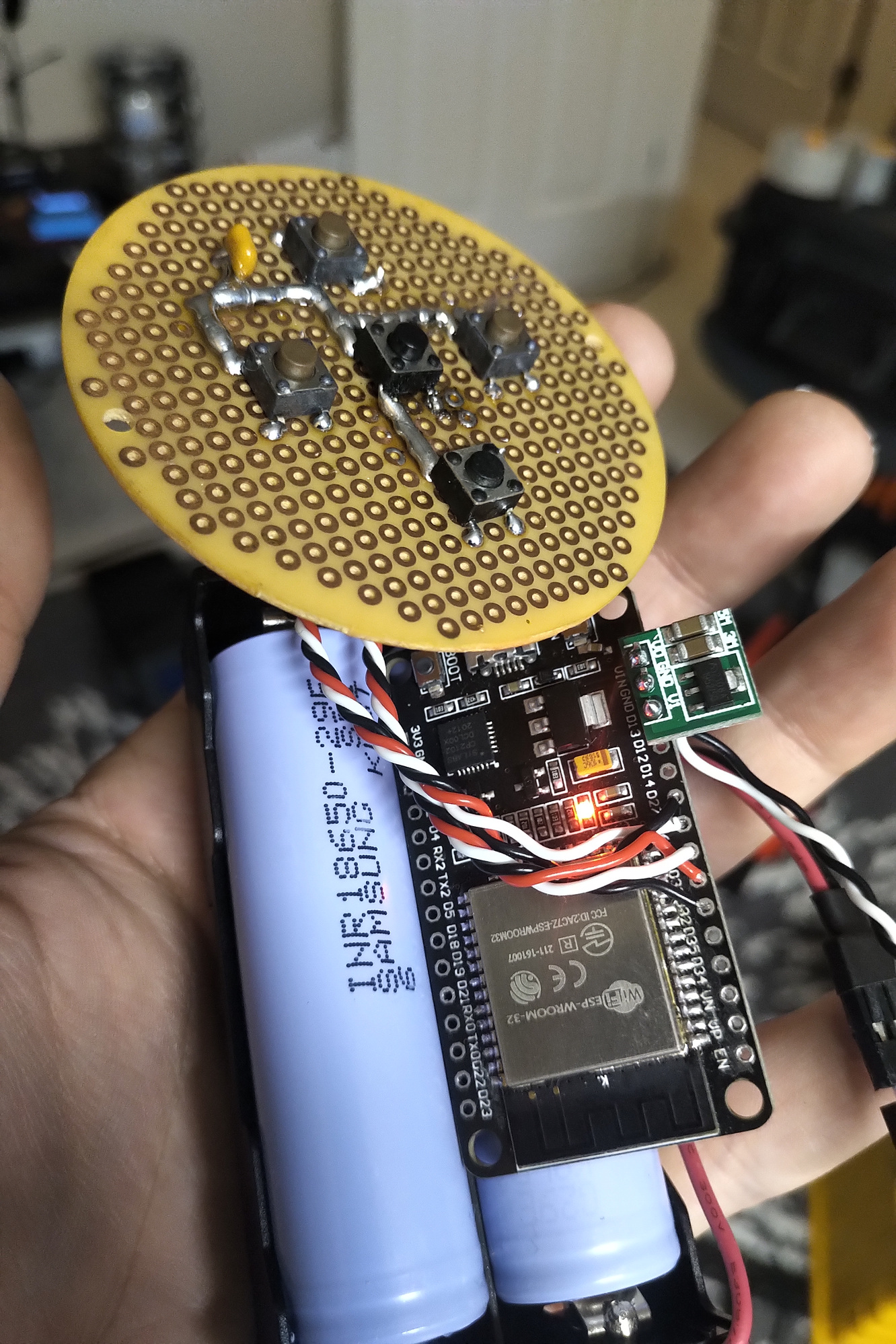
Using some parts laying around, I soldered up a beautiful button board for an ESP32, and wrote the ArylicHTTP library for interfacing an ESP32 with Arylic devices via the HTTP API.

Using the previously mentioned library, I build a small firmware package for the ESP32 which will grab button presses and interact with the API accordingly. I will need to make some modifications to work with the jog wheel once that arrives.

Firmware on GitHub

There are some improvements to be made for sure, currently the device supports only 5 functions:

  • N: Set volume to 80%
  • S: Set volume to 40%
  • E: Next track
  • W: Previous track
  • C: Pause

The next two feature to work on are WiFi provisioning, and better volume control - Using the getPlayerStatus call I would like to fetch the existing volume and modify that vs setting an arbitrary level.

The firmware was designed to, on button press, wake and connect to WiFi; once the WiFi connection has been established, button presses will preform the above actions with minimal latency. After a period of inactivity, 15 seconds, the device will go into a low-power deep sleep mode to preserve battery power.

Some spare parts, an ESP32, and LiPos I had laying around, and now I’ve got myself v1 of an Arylic remote!

I am thinking a single RGB LED can accomplish all of these things, here is going to be the plan for my firmware:

  • Blue flashing
    – Unconfigured / Setup Mode

  • Purple flashing
    – Connecting to WiFi

  • Purple solid
    – Connected to WiFi

  • Red
    – Number of flashes indicate error code
    — Error connecting to WiFi
    — Error when making API call
    — Low battery

@mclarkdev Matt.

It seems a lot more professional software than I have managed as it’s certainly not my day job :joy:

I’ll update the functional specification and e mail it to you. I am quite happy to step aside on the coding side if you would like to contribute directly to this project.

Another option is that I could concentrate on a DLNA version which would eventually have a huge market of devices it could work with :slightly_smiling_face:

The idea is that we actually manufacture a device developed by forum members :slightly_smiling_face:

I am using the Volume ++ & Volume-- Commands

These commands are well suited to the Rotary Encoder Control :slight_smile:

Regards, Kevin

@KolfMAKER @zpl1025 @Hydro3 @mclarkdev

I have updated the HW Design Drawings & Prototype Hardware ready for testing next week.

Looking great,

I’ve already added encoder support to my code, so if you decide to try out my firmware, be aware that we used different pin numbers! You will need to update the configuration in Pins.h first.

Here is what I have collected so far for a Requirements overview document. I also have project / task tracking setup on my OpenProject instance, and can grant logins to anyone who wishes. (below text exists as a wiki page)


Processor

The main processor the device is an ESP32-S2-WROOM, a device more then capable of preforming the task at hand. Chosen for it's low cost, WiFi capabilities, and Arduino integrations, this processor will allow a wide range of remote control tasks and even allows for OTA upgrades. This processor is so powerful in-fact, we will be under-clocking it to the lowest possible speed which still supports WiFi. Normally running at 240MHz (2x CPUs @ 120MHz), we under-clock our device to just 80MHz (1x CPU @ 80MHz) in order to save as much power as possible from the tiny LiPo pack attached.

WiFi Connectivity

Using the ESP32 as it's core, the device will communicate with Arylic devices via the HTTP API.

Power

The device will be powered by a single small LiPo cell, and due to the low-power nature of the device, should last quite a while.

  • Single Cell LiPo (500mAh?)
    • LDO Regulator for stable processor voltage
  • Ability to self monitor battery voltage
    • GPIO drives a transistor to enable a voltage divider
    • ESP32 reads analog voltage across divider
  • MicroUSB input for battery charging

Input

A simple device, the remote has just a simple jog wheel for volume control and 5 buttons which can preform a variety of actions.

  • A directional pad will be connected on pins N(#), E(#), S(#), W(#), S(#)
  • A jog wheel encoder will be connected on pins A(#), B(#)

Status LED

A single RGB status LED will be used to indicate all modes and statuses of the device.

  • A status LED will be available on pins R(#), G(#), B(#)
  • Different colors and pule counts will indicate device status
    • Purple solid
      • Connected to WiFi
      • Fades to [0] with inactivity
    • Purple flashing
      • Connecting to WiFi
    • Blue flashing
      • Unconfigured / Setup Mode
    • Red
      • Number of flashes indicate error code
        • Error connecting to WiFi
        • Error when making API call
        • Low battery

BOM

  • Encoder [Link] [$8.95/ea]
  • Encoder Board [Link] [$1.50/ea]
  • ESP32 Devkit [Link] [<$10/ea]
  • Battery Hypervisor [Link] [<$.80/ea]
  • RGB LED

This is a very good point to emphasise. If using the drawings that I have posted attention needs to be be paid to the PIN Configuration. To be more precise

#define PIN_DPAD_N GPIO_NUM_26
#define PIN_DPAD_E GPIO_NUM_25
#define PIN_DPAD_S GPIO_NUM_33
#define PIN_DPAD_W GPIO_NUM_27
#define PIN_DPAD_C GPIO_NUM_32

#define PIN_ENC_A GPIO_NUM_12
#define PIN_ENC_B GPIO_NUM_14

#define PIN_LED_R GPIO_NUM_4
#define PIN_LED_G GPIO_NUM_2
#define PIN_LED_B GPIO_NUM_15

Great response and input @mclarkdev Matt. Thanks for thinking & doing with us! :sunny:

Very interesting you mention to under-clock the ESP, resulting in low power consumption, but still being able to communicate via WiFi.; brilliant! :+1:t3:

Status LED
Concerning the colors chosen, for the proto typing, any color is fine, as long is it distincts one functionality & meaning from the other.
In the final product I would prefer White for WiFi, like with the Arylic products (white = WiFi, blue = Bluetooth).

@KolfMAKER @zpl1025 @Hydro3 @mclarkdev

I have tried to consolidate @mclarkdev lamp colours with the possible faults we initially listed in the FDS. It looks like this:-

My main comments or propositions are:

  • Avoid Blue for now. Intrinsically linked with BT on Arylic Devices. Also there could still be a BLE Version of this device !
  • Q. On configuration - Good Idea to distinguish between WIFI OK and Comms ESP32<>Arylic OK. This could be Arylic not paired (during config) or as Matt states an Error Making API Call (during normal use).
  • Q. Is it worth having a colour reserved for the battery ? e.g. Yellow ?
  • I am pretty sure we will all be agreed on a flashing red for any “malfunction” :slight_smile:

Looking forward to your input, Kevin

@KolfMAKER @zpl1025 @Hydro3 @mclarkdev

With a view of moving forwards to the required hardware (BOM) for Prototype V1 & V2 there are a couple of decisions that need some thought/discussion.

  1. Power ON - OFF Switch ?
    I am thinking as the device doesn’t need to be used constantly e.g. only when listening to music a little switch to knock it off completely is not a bad idea.

However @mclarkdev do you think it will be possible to put it to sleep and wake up with a button touch ?

  1. Factory Reset Microswitch
    I am presuming not a bad idea to have one.

@mclarkdev do we need another input to the MCU or can we do this off the the microswitches on the ESP32 e.g. mount the board to make them accessible from outside the casing ?

Looking forward to your feedback, Kevin

No power on / off switch. One of the wonders of the ESP32 is it’s super low power consumption in a deep sleep, device can last for months.

The firmware is currently designed to enter a deep sleep after a 12 second period of inactivity (configurable). The device will then wake up at the press of a button.

I am not sure we need a ‘factory reset’ switch as long as we have a way to enter the configuration mode. Once in the configuration mode we can have an option to clear all configuration values for transfer of device ownership or something.

My idea for Configuration mode is a pin-hole micro switch, which when pressed, will boot the device into the BLE Server configuration mode to be connected to by the app.

I plan to use an additional input to achieve this. Once we go to a production device, we will not be using the whole dev-board, but instead just the ESP32 module itself.

Wow! Wow! Wow!
I haven’t read this thread for quite a while (since mid of November last year, I guess), and I’m now less or more out of active coding for personal reasons, but… THIS IS AWESOME! You guys are awesome! Really great work, and I really appreciate it… :smiling_face_with_three_hearts:

I’m curious what the result will look like and how it will work. Brilliant. :smiley:

1 Like

I get the remark of @mclarkdev , especially the power consumption of the ESP. As long as the ESP is the only component taking power, and we do not have the need of a Mini on the volume knob, perfect.

Question from my side
So we use the ESP to connect to a Arylic device, or group of Arylic devices, and set commands to control it. Right?

Yes we do need to define how it will work re Master, Slave, Group. This will be purely software and functionality and shouldn’t effect the hardware design. @mclarkdev software is a lot more powerful than I had ever imagined and I am sure it will have much wider usage than our simple volume knob :slight_smile:

I would like to familiarise myself and use Matt’s software before coming up with any firm suggestions. My next moves are:-

  • create parts list for prototype V1
  • test and understand Matt’s approach
  • Finalise Status lamps definition & colours etc.
  • Test Prototype V1 Fully with Single Device connection
  • define/discuss/propose Functionality and Configuration with multiple devices

In the meantime I will also prepare something in the FDS that will help us work through the Multiroom side of things.

Regards, Kevin

Why I mentioned this is following. If in the end we need to control volume of a group of Arylic driven speakers, we might need an Up2Stream Mini in the volume know. If that’s the case, we get a different kind of power consumption for the knob.
If we can do just with the ESP, that’s fine. But I am curious how we than handle groups of speakers to be controlled by the knob (in a user friendly way).

:nerd_face: