Hi,
I want to relocate the Volume, tone and bass knob. Has anyone successfully done it? Can anyone advise?
I know i can get the extension board but it is FUGLY and i kinda like knobs.
Thanks!
Hi,
I want to relocate the Volume, tone and bass knob. Has anyone successfully done it? Can anyone advise?
I know i can get the extension board but it is FUGLY and i kinda like knobs.
Thanks!
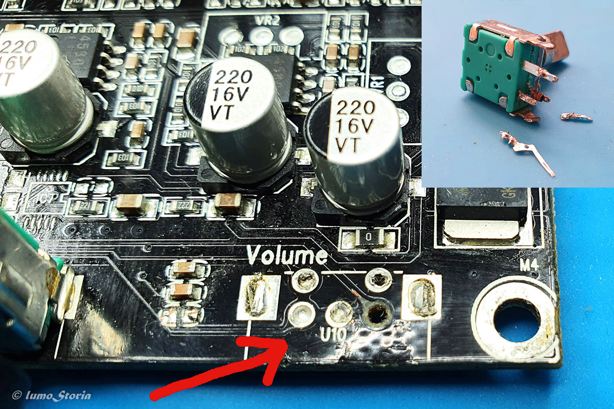
OK, first of all a picture showing how to do it - not! 
I used a simple soldering iron (not even a cheap one) and failed miserably. You should only try this if you know what you’re doing (I didn’t know) and if you have one, definitely use a desoldering gun (cheaper than a broken board).
If it was only the volume knob, I would suggest to just use two push buttons (one for “Volume Down”, one for “Volume Up”). They can be connected easily (with just some resistors) via the 9pin-connector of the board (at least if we talking about an Up2Stream Amp 2.1 board). However, I have no idea how to do the same for the tone and bass knobs.
Would be interested to hear when you succeeded  .
.
Regards, Sven
I was looking for relocating tone and bass knobs, finally I only relocate the volume with buttons.
Unless you are good good with soldering iron, I dont recomend you to desoldering the knob. Other option that you can try is find the same knob and weld the cables in the bottom part of the board without taking out the one that comes with the board, in this case if you fail you only have to cut tha cables and the board goes to the original state, I made it for some functions like the power button (Always at your own risk of course).
Sounds like a great idea… only problem is where do you get the knobs from? I know they are digital type, any advice? thanks
Looks to me that you have done a better job then what i would have done! hahaha i am looking at the idea from @Joanb14 about soldering aotner buttonfrom the bottom.  its a good alternative.
I figured the volume knob is a Rotary Encoder Code Switch.
Anyone know the model number? or the details? like if it is an Absolute or Incremental?
I was thinking in another option also, in Arylic there is a external volume knob, that you can buy from their shop, then you only need a cable and find which pin is which.
Joan
Hey Sven,
for desoldering you need a proper heatgun and add flux to the soldered points.
Makes it a lot easier
I know, I know  . Meanwhile, I got me a desoldering gun (ZD-985) but now it just sits on the bench, waiting for the first desoldering job. Could try to desolder also the bass and tone knobs
  - no, don’t think so. These knobs are not of too much use to me externally.
The needed rotary encoder has to be incremental. The encoders of this type are typically very similar, returning a 2-bit Gray code via three pins. They mainly differ by the number of “clicks” that are performed per one full rotation of the encoder. You can just count the number of “clicks” of the Arylic encoder by rotating it 360°. However, it is not that important whether the replacement encoder has more or less “clicks” (just changes the number of rotations needed for a specific volume change). Another difference is whether they have an additional switch (when you push the encoder knob in) → two additional pins. The Arylic encoder has this switch and uses it to toggle between modes. Therefore, it might be a good idea to get one with a switch, too.
I got my replacement encoder from a German electronics store, here is the link to the product I chose (ALPS - STEC11B):
https://www.reichelt.de/drehimpulsegeber-20-impulse-20-rastungen-horizontal-stec11b09-p73915.html?&nbc=1
The price was about five bucks. You can also find these encoders in shops selling Arduino accessories since these encoders are used a lot in Arduino projects. Hope this helps.
Regards, Sven
i did look at that alternative except there is no external volume knob option for the 2.1 amp… also want to relocate the other knobs so the external knob sold by Arylic isnt an option.
k
Hi Sven. thanks for the reply. I did look at the ec11b varieties with 5 pins A-E. Can you share your experience.
A - ground
B - gpio1
C- gpio 2
D - ??
E - ??
Thanks in Advance
Kervs
D and E are the pins of the push-down switch of the rotary encoder. These are open by default and are shortened if you press the knob. The Arylic board uses this switch to toggle between modes (WiFi, Bluetooth, etc.).
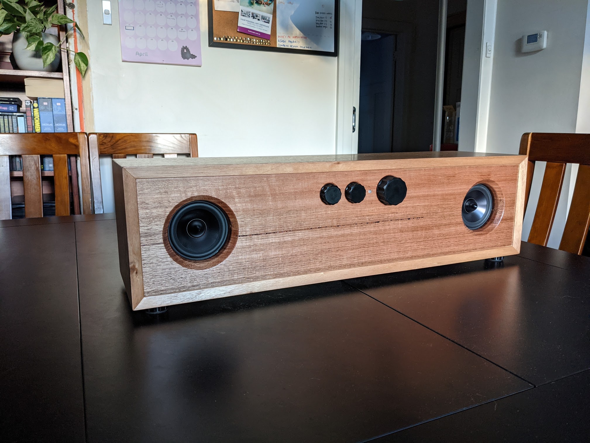
I have done this.
I have made a couple of ‘boombox’ speakers using the 2.1 amps and relocated all of the rotary encoders to a new front panel. I also changed the rotary encoder function so that bass knob press = play/pause and treble knob press = skip/next. Volume press I retained the original function (change mode).
I don’t have any photos as I have given them away to friends, but there are a couple of things to note:
First - I was not able to salvage the original rotary encoders. All three of them were damaged when I was attempting to remove them. I replace them with these.
Second - It was a challenge to remove them without damaging the PCB traces. I found that it needed a fair bit of heat (~350+ degrees). I held the soldering iron for approx. 10 seconds per pin and used a solder sucker to try and get as much solder out of the through hole as possible.
I regret not taking more photos, but I soldered headers in place of the rotary encoders on the PCB - they are a perfect size for 2x3 headers if you remove one of the middle pins. Then I used ribbon cable to connect the new encoders to the board. Then I made up a little voltage divider as per the manual for pause and next buttons and connected the bass/treble momentary switch pins to the adc button input via the divider.
It all worked pretty well - except I had massive issues trying to set up the button divider based on the specs - nothing published seemed to work, it was a lot of trial and error.
Update: I should note that, I am currently in the process of doing this again - and this time I have decided not to remove the original encoders. I am going to just piggyback off of the original pins (solder small extension wires to the underside of the board) and run the new encoders in parallel. I haven’t tested this yet, but I don’t expect there will be any issues. The circuit resistance will change but I don’t think it’ll impair the encoder function - I will report back. This method means no potential damage to the traces by not removing the original encoders, given they are not really salvageable when removed anyway - so either method requires buying a new set. Luckily they are relatively inexpensive.
Hi Rob,
Congratulations for your desoldering job. I broke the encoders and the PCB traces (see picture in my post above), you only broke the encoders. One day a real master will appear and will break neither the PCB nor the encoders  .
.
I’m not sure if it is possible to run the encoders in parallel. Depending on the position of the encoder knob, gpio1 and gpio2 will have a certain logic value (HIGH or LOW). If you just connect a second encoder in parallel, the gpio1 and gpio2 of both encoders will influence each other. Maybe it is possible if you set the knob of the encoder on the board to a specific position so that it’s gpio1 and gpio2 are either both HIGH or both LOW.
But maybe it’s not a good idea to think too much about the theory but just do it. I suppose, other forum members (including me) will be curious whether it works.
Best regards,
Sven
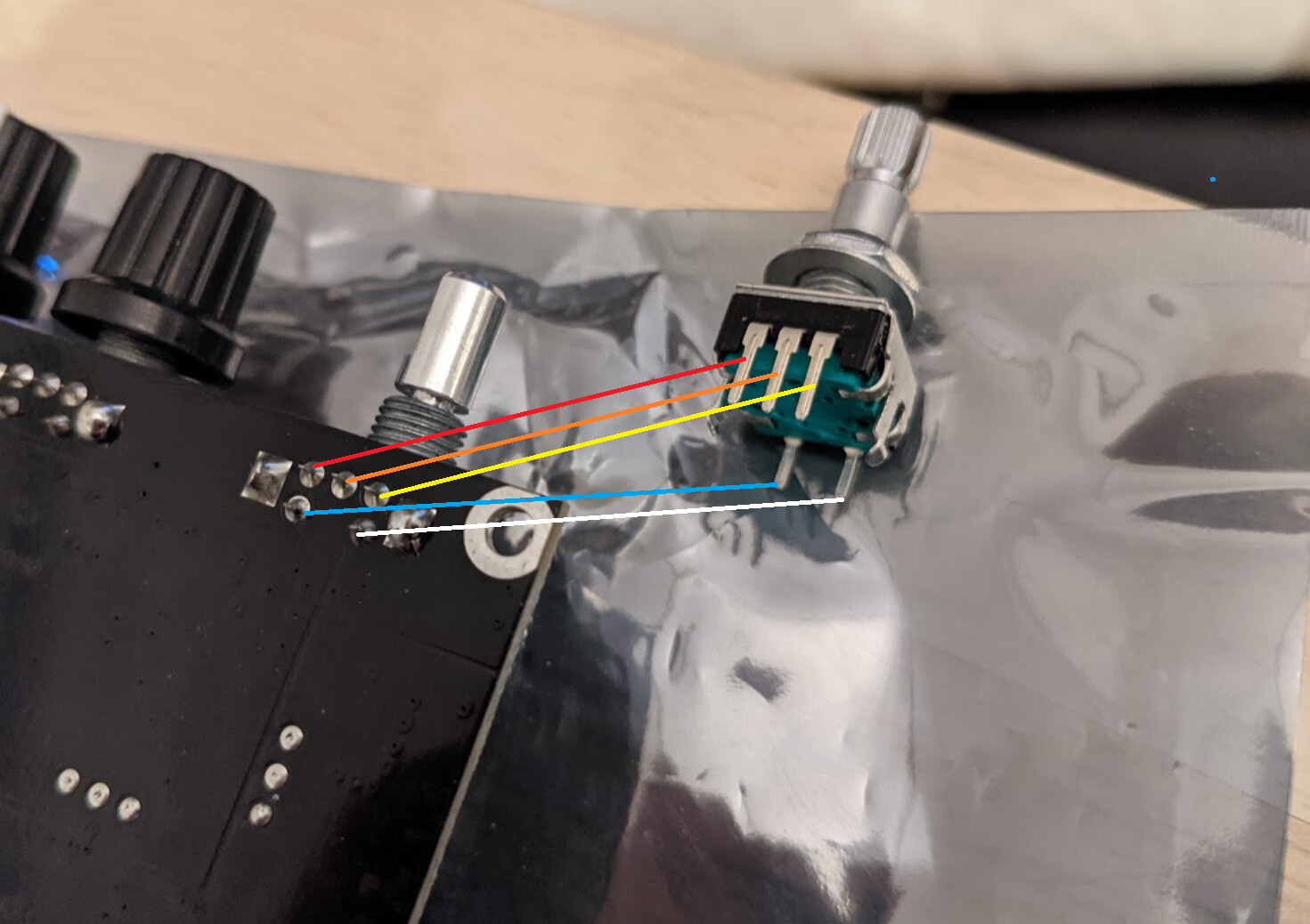
So I took your advice and avoided putting too much thought into the theory of whether it is or is not possible - and I can confirm - it is possible!
Actually, I didn’t even solder anything up, I was able to get it to work by just holding the new encoder up against the existing pins and rotating it a bit. Worked perfectly. This is the orientation:
The blue/white lines can go any way around as they’re just a momentary switch anyway.
Congratulations  .
.
NICE!!!
Ok… after much searching and frustration i have prototyped the electronics and want to share.
The parts for the rotary encoders come in 2 categories …
“Panel-mounted” is made by Bourne - Part number starts with PEC11R
PEC11R-4xxxF-Sxxxx (“S” indicates switch which IS NEEDED)
Data Sheet: https://docs.rs-online.com/6487/0900766b813ecfbe.pdf
Here is the Site where to can buy the different variety according to your project (search PEC11R):
https://uk.farnell.com/search?st=pec11r
“Smooth shaft” is made by ALPs - Partner Number starts with EC11E
DataSheet: http://www.farnell.com/datasheets/1676943.pdf
Here is the Site where to can buy the different variety according to your project (search EC11E):
http://www.farnell.com/datasheets/1676943.pdf
Tip:
Take the time to understand the Product numbers - It helps explain the number of “clicks”, Shaft length etc.
I have tested 2 models of the PEC11R and it works for me.
Have to say a BIG thanks to @EthanEsrah for pointing me in the right direction!!
Should be done with my project in 2 weeks and will post it here…
Lets keep sharing !!