I have recently finished an amplifier build which includes a V3 mini and DAC board, which I am very happy with.
My next project is a standalone unit using a V3 Pro board with a ES9018 I2S DAC board and an additional input for an amplifier using a DP latching relay.
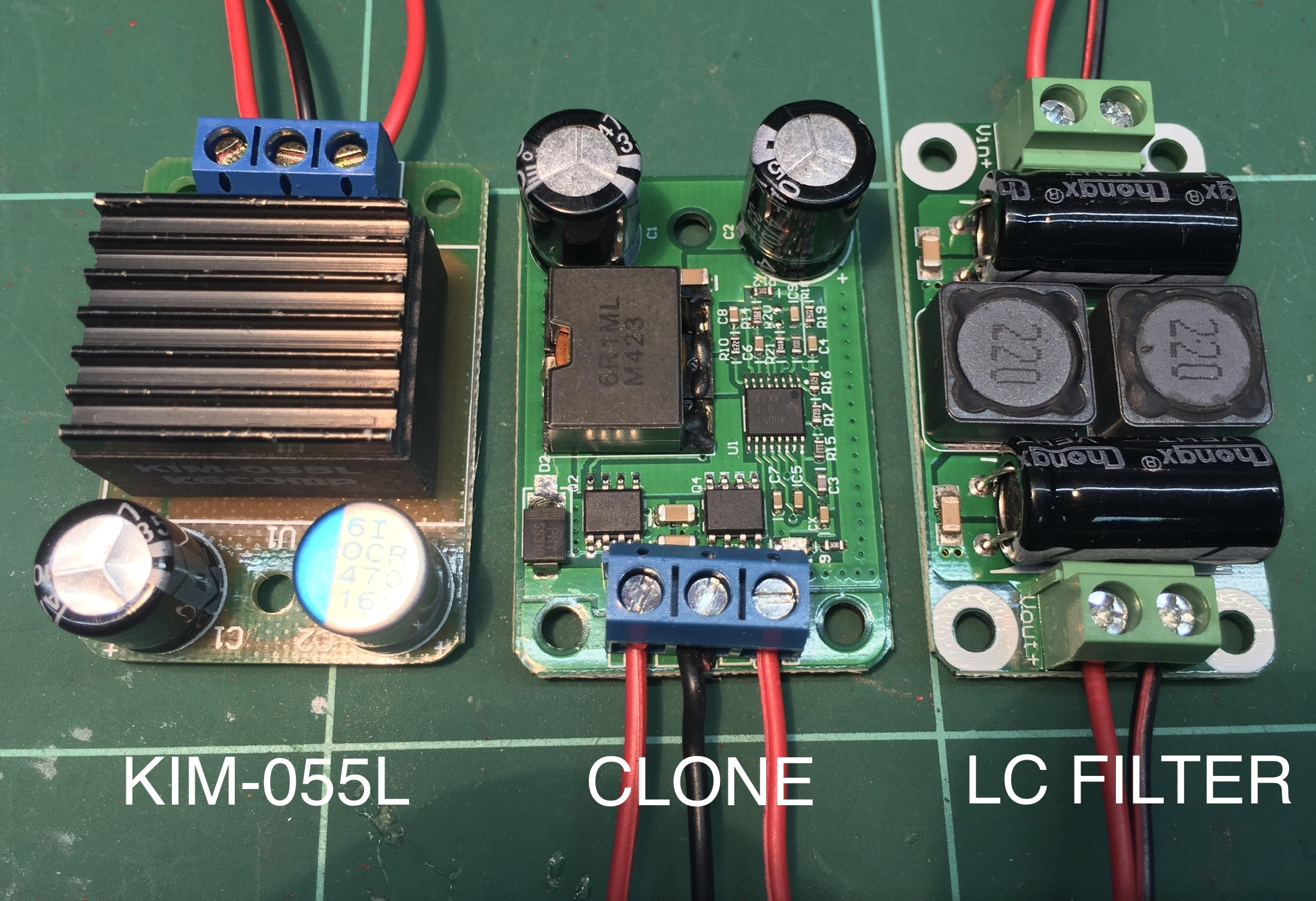
I have been deliberating over a power supply for it, the DAC board requires 12v DC and the Arylic board and relay 5v. The thoughts are that I just use a 12v SMPS and a 12 - 5v converter (I have a KIM-055L converter) I was reading that if you use a linear regulator then the 5v supply will be less noisy by reducing the power supplies HF switching noise so I thought that it would be interesting to see if this is the case.
I found a LT1963 low noise 5v linear power supply module on eBay, and it’s on its way to me now. I also saw a LC filter module for switching supplies so I bought one of those as well.
I have an old CRO, so once I get all the parts I’ll rig it up with a dummy load (12v light bulbs should be ok I think) and see if there is any noticeable differences in the DC noise.
My other option for a power supply would be fully linear, but I want to see the results of the above before making any decisions.
I hope this might be of some interest to you guys, I’ll follow up with another post once I have some results, meanwhile, I am open to ideas and constructive comments.
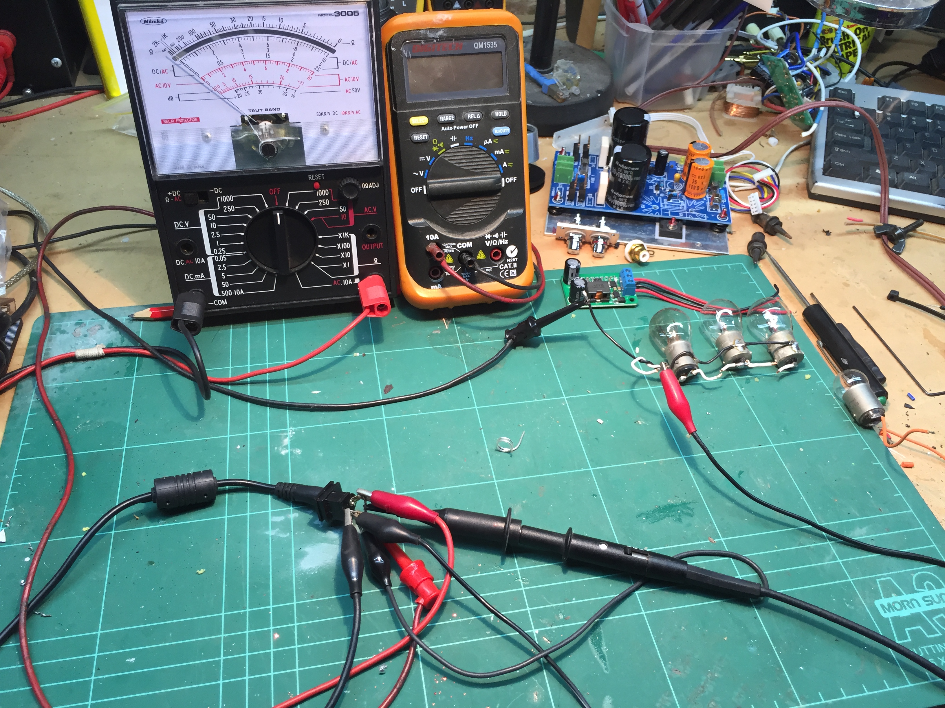
Analogue multimeter showing voltage, digital MM showing current, scope probes set at x10 (for a 1 volt signal, the scope input gets a 0.1V signal). The power supplies loaded with a resistive (12v 6.5w light bulb) load and the 5v converters with a 5w bulb.
With the parts that I currently have available, I carried out the following:
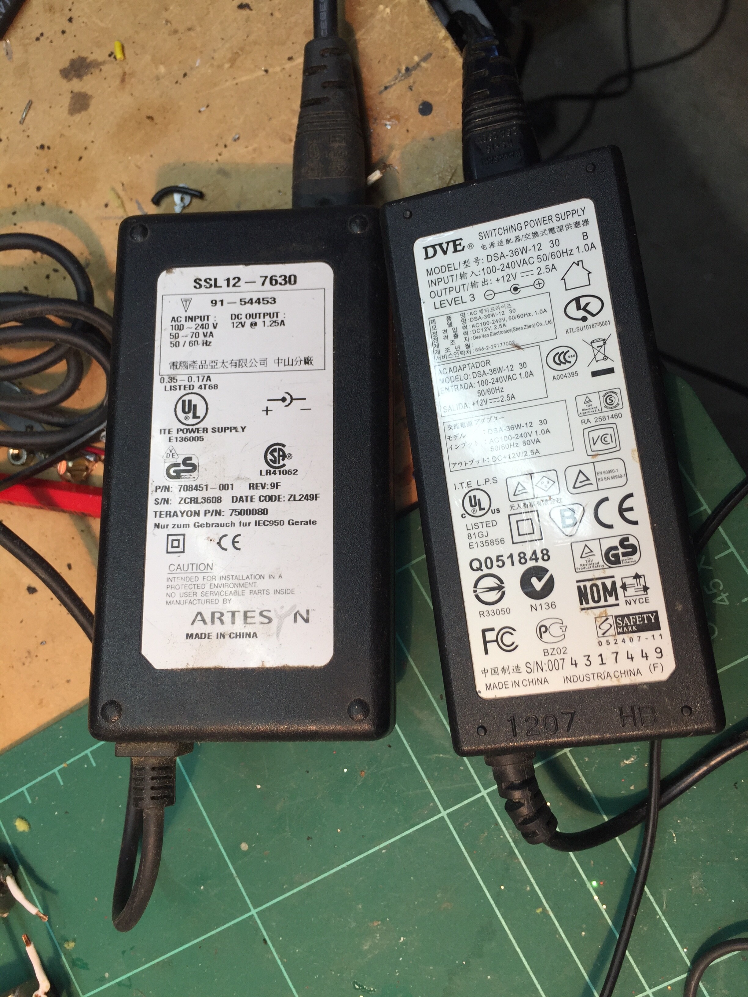
Test 1: Using a generic branded SMPS rated 12V 2.5A
Test 2: Using a generic branded SMPS rated 12V 1.25A
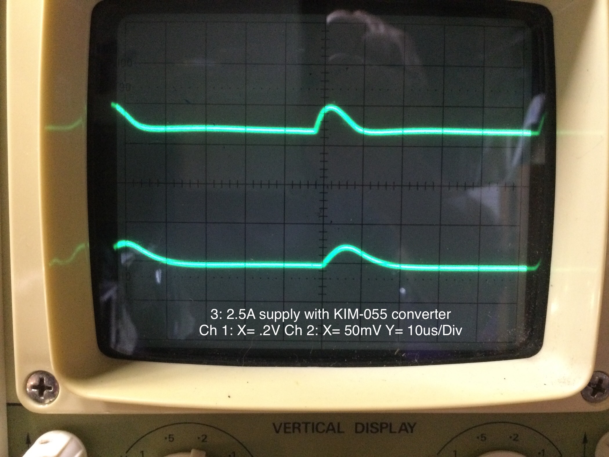
Test 3: Using the 2.5A PS with a KIM-055L 5V converter
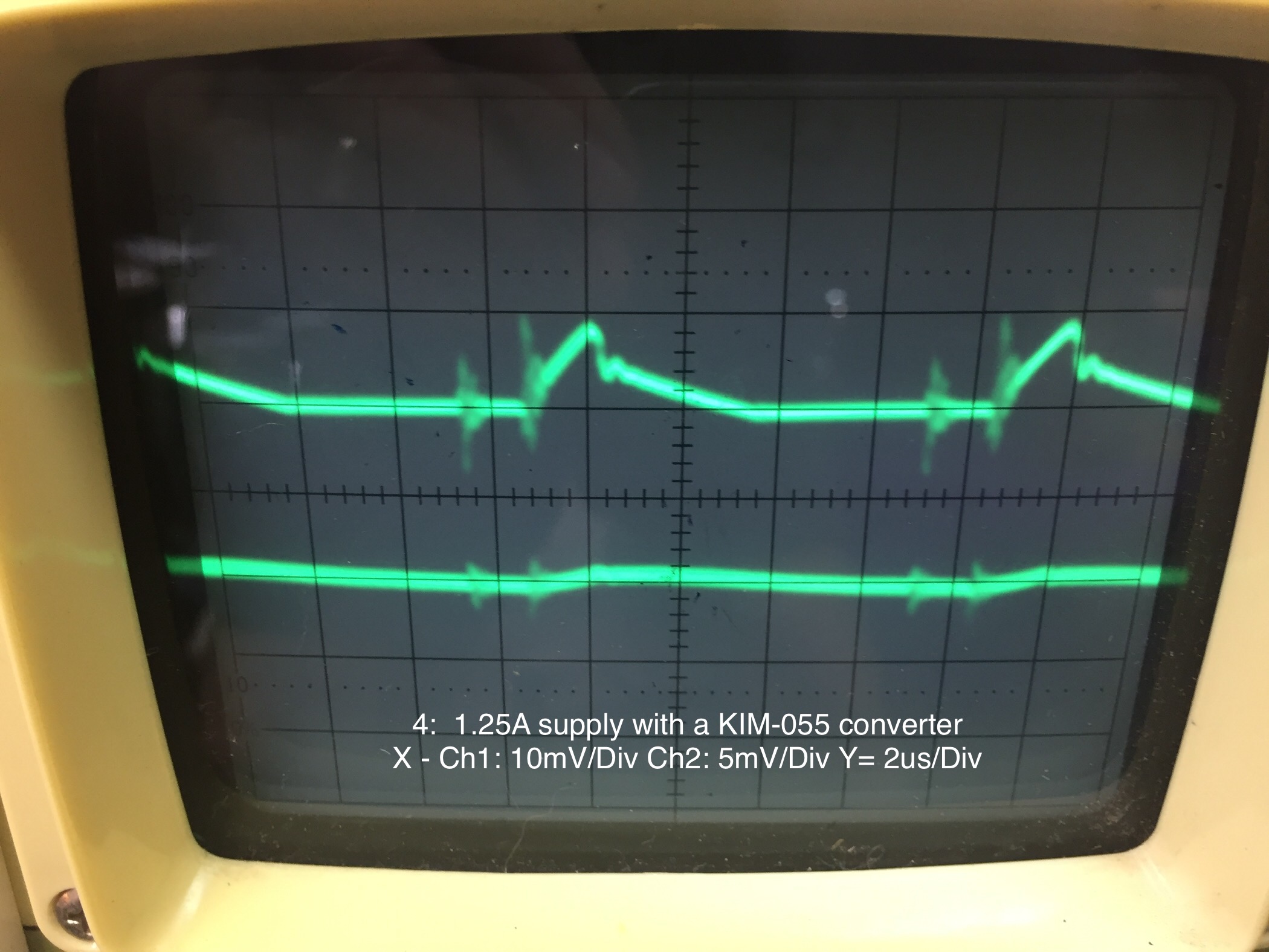
Test 4: Using the 1.25A PS with a KIM-055L 5V converter
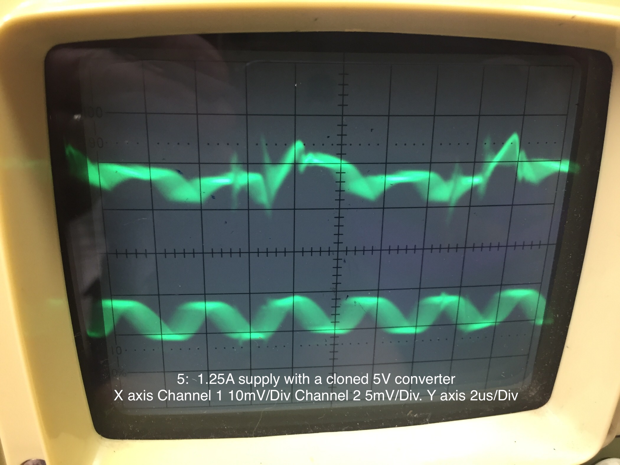
Test 5: As test 4 but using a cloned 5V converter.
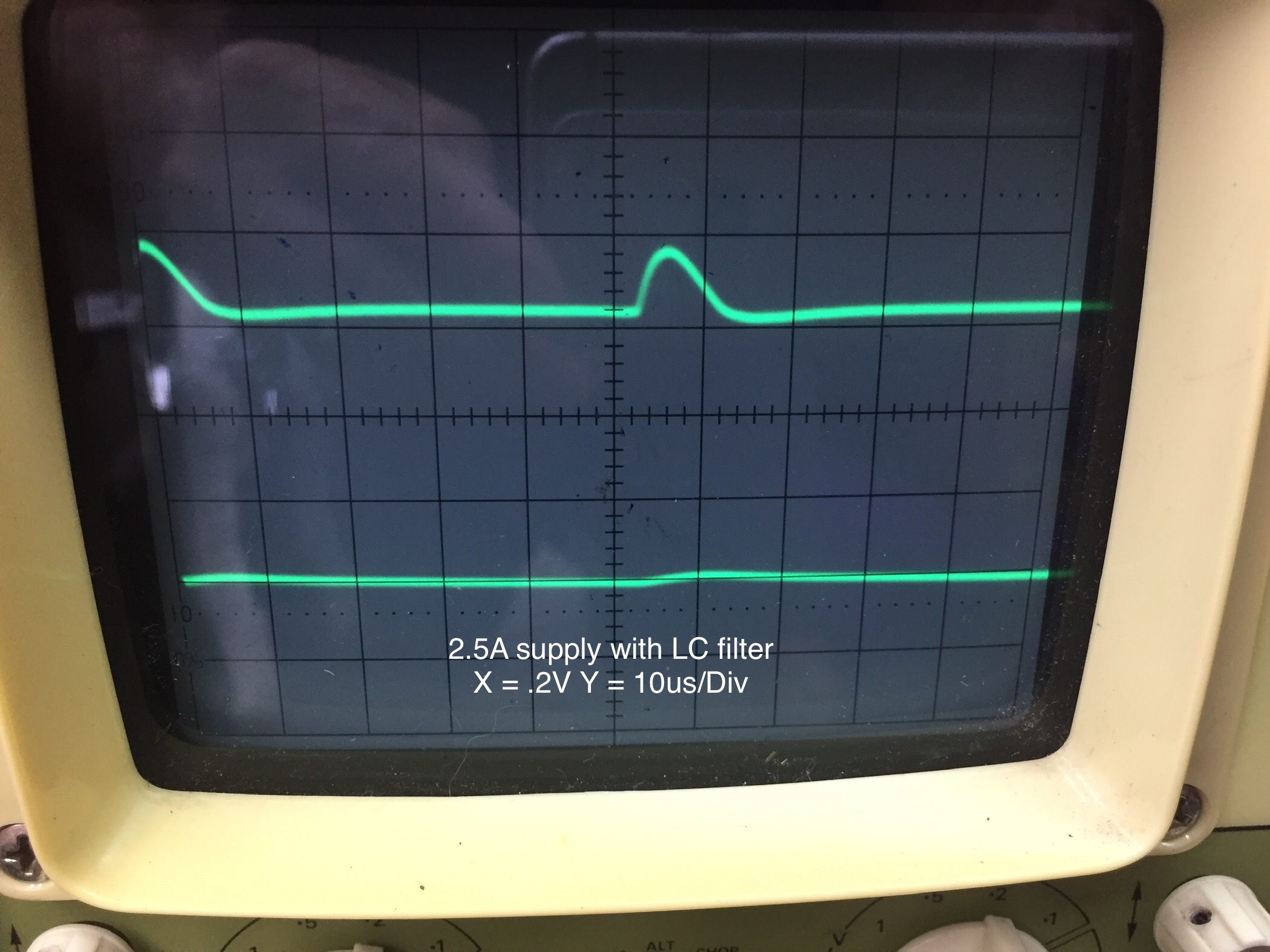
Test 6: The 2.5A supply with the inline LC filter
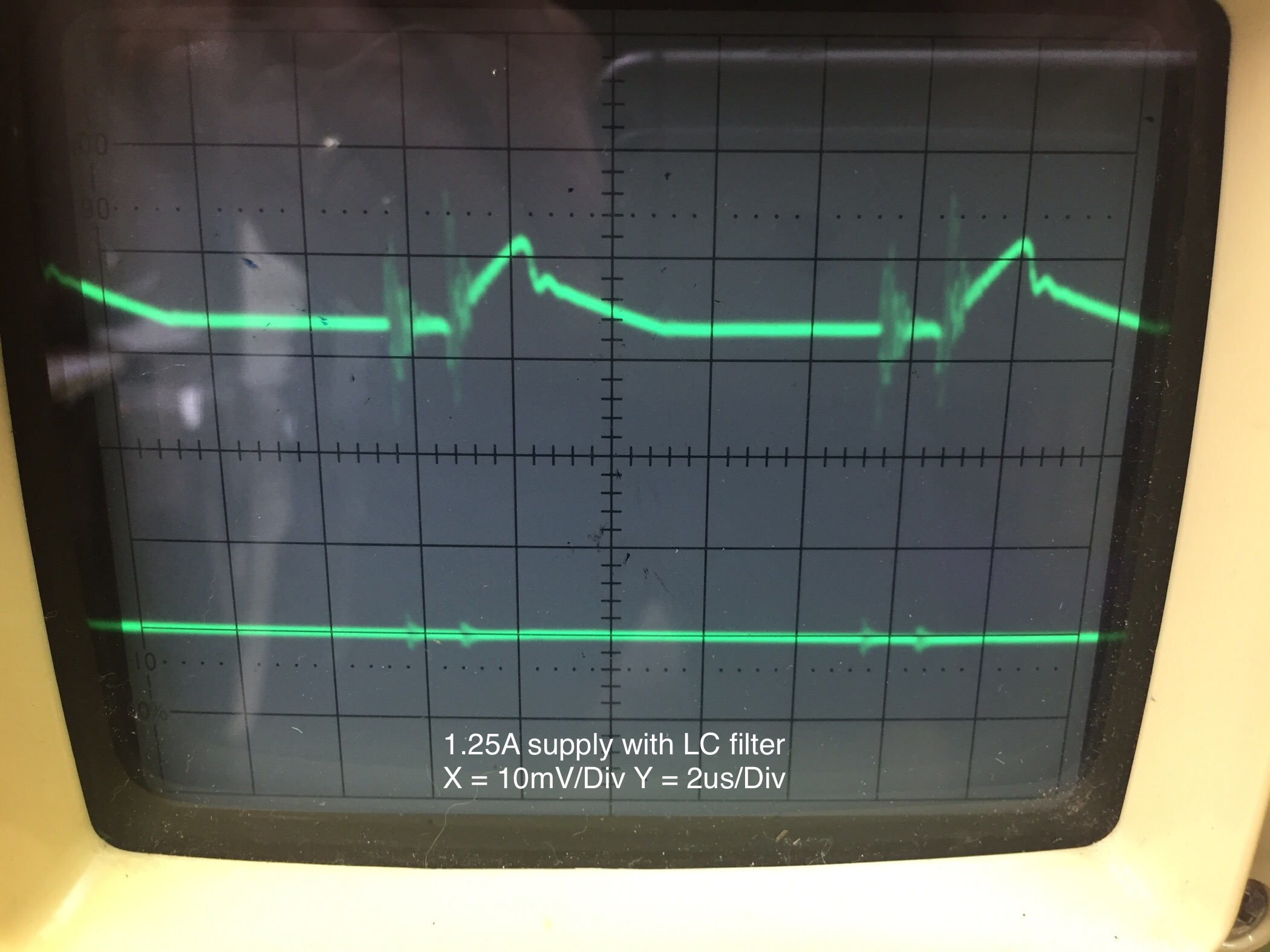
Test 7: The 1.25A supply with the inline LC filter
Results so far
Test 1: When loaded the supply could only achieve about 80% of the rated 2.5A before the voltage dropped off. Trace 1 @ .55A load
Attached photos show results.
In photos showing two traces, the upper trace is channel 1 (power supply output) and the lower trace being a converter or filter:
Conclusions (so far)
The cheap switching power supplies and cloned converter that I tested appeared to be fairly noisy, the switching frequencies can be seen on the traces. The LC filter (which is a combination of Inductors and capacitors tuned to block certain frequencies) appeared to remove some of the power supply switching frequencies and might be worthy of addition tests and investigations.
I haven’t conducted any listening tests, I am always weary of ‘snake oil’ type magical fixes/upgrades to audio equipment, for all I know, manufacturers who power their equipment with switching supplies might already include additional filters to clean up power supply inadequacies.
Future tests will include using a linear 12 - 5v converter used with a switching supply and results for a fully linear supply.
Disclaimer:
Please note that I have no formal training in electronics, the knowledge I have gained is purely as a hobbyist, the above tests were carried out on equipment that was available to me, more up to date equipment such as a storage or digital oscilloscope would be required to achieve more accurate results than I was able to achieve.
Hi Steve, obviously I should have searched more widely in the forum than just plate amp entries to find your work so far in dealing with power supply issues. Thanks for the heads-up.
I noticed your disclaimer that you aren’t formally trained; I’m even further down the food chain, so I’m at a bit of a loss to interpret what I’m seeing and I need to do some learnin! First off, is the X-axis actually voltage and Y time, or the other way around?
Anyway, in Tests 1 and 2 (and most of the rest) why are there 2 peaks in the trace, is this a ripple on a DC or is it an illustration that the PS cannot supply a constant voltage to the load when a short square pulse is applied?
In regard to the differences between the 2.5 A and the 1.25 A supplies, is it the case that the 1.25 is awfully noisy and the 2.5 not so? And is the interpretation of the figures that the LC filter isn’t really suppressing any noise on the 1.25 A supply and just reducing peak voltage for the 2.5 A supply?
Yep, it looks like my labelling of the photos was a little incorrect y axis (vertical) is voltage and the x is time.
I’m just a hobbyist who enjoys playing around with this stuff and where I can, helping others.
Yes, the pulses are noise, and the LC filter does assist in negating these, so I would recommend their use.
The two pretty crappy supplies I tried the 1.25A supply was quieter V was 10mV / division whereas the 2.5A supply was shown as .2V / division (200mV) this would be fine for LED lights, but not for audio use.
Hope this helps.
Hi Steve, you’ve definitely helped, the penny has now dropped as to what your results show, thanks for guiding me through (and providing the experimental results!).
PK