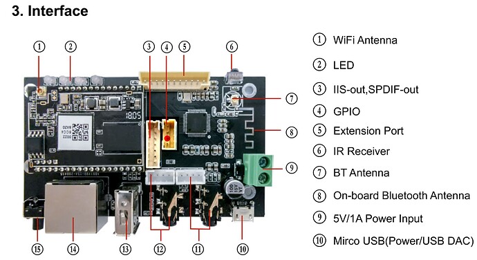
Hi If I’m right you could use the 3.3v on the Ph2-4pin connector (number 4 in the manual named GPIO) next to the 7 pins connector (numbe 3 in the manual named IIS-out,SPDIF-out) as per attached picture. The ground beeing the first pin and the switched 3.3V the second. (not sure of the numbering order, I didn’t want to remove my board from the chassis where it is wired on. So no access to the solder side to check). Anyway it’s the red dot on the picture
If I were you I would Isolate the command electronics of the relay from the Amp v3 board with a photocoupler to make sure there is not unwanted leak or interference.
Hope this helps
Enjoy!
Nobu.
