Hi If I’m right you could use the 3.3v on the Ph2-4pin connector (number 4 in the manual named GPIO) next to the 7 pins connector (numbe 3 in the manual named IIS-out,SPDIF-out) as per attached picture. The ground beeing the first pin and the switched 3.3V the second. (not sure of the numbering order, I didn’t want to remove my board from the chassis where it is wired on. So no access to the solder side to check). Anyway it’s the red dot on the picture
If I were you I would Isolate the command electronics of the relay from the Amp v3 board with a photocoupler to make sure there is not unwanted leak or interference.
Hope this helps
Enjoy!
Hello, yes this really helps and gives me a start where to look on the bord and how to measure. While 3.3v is not ideal it could be enough to pull the relay.
Maybe a future arylic board has a 5v switched pin on board. It would be a great feature:)
I would advice not to directly use the switched 3.3 supplied to drive the relay as it may pull to much current. If you need some more help I can provide you with a schematics based on a couple of common components to securely drive the relay.
Hi @Nobu, is there any change you could provide a schematic for this?
I’m trying to drive a relay using the Gpio pins. I tried using a little transistor as a switch, the Gpio pin connected to base but I’m not getting the right results.
Would love to see a little schematic that would make this work.
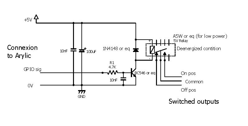
Here a schematic of a quite simple circuit you can use for inspiration. I wouldn’t trust a 3V nor 5v relay for switching the main as inrush or surge current could be quite high at closing or opening the contact. Hence it can remain closed due to the current flowing through the contact preventing it to turn off, and sparkles can occur at closing or opening that can damage the small switch contact surface in this case. Low voltage relay means high current in the command coil if you need a good contact or opening force (the ratio: current / contact surface sets the mechanical force required to open the contact).
Plus at start, the current rises a lot, hence soft start circuits…
But you still can use this circuit even in 3V to trigger another like a soft start one. This would allow a good galvanic isolation between the power circuit and the arylic board.
Send me the drawing of your circuit and indications of the symptoms, so I can guide you to understand why it doesn’t fit the needs.
Another path to explore is instead of switching off the power supply, there may be a way to turn of the amp via a low power signal.But this would mean you have a small idle power consumption, as if you use the remote command to turn off a ‘modern’ device.
Give me the reference of your homeamp I’ll be happy to dig in.
I’m sorry I wasn’t clear in my previous post. I’m not trying to switch mains, but a 12v light. I need the light to turn on when the board wakes up from sleep mode.
I tried driving the relay (which is on a board together with a optocoupler) using a transistor, much like in your schematic.
I will try your schematic first.
What I since found is that in ACP Workbench I can set one of the pins to “OUT CTRL” which in my understanding sends a signal when the board wakes up, but i’m still trying to find some more information about that.
Hi,
as I received the same question from another member I didn’t realized it was not the same need/person…!!! the other one trying to switch on/off the main…
I don’t have ACP so I can not comment. But as mentioned in the relpy nr2, in the same post, I’m quite sure the pin (#3) - red dot on the picture - would do the job, the pin (#1) being the ground.
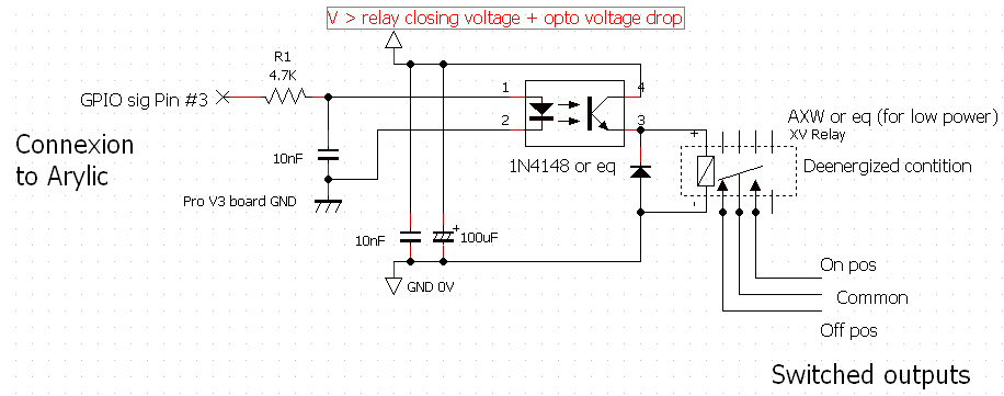
Depending on the relay you are using, make sure you have enough current driving the opto so that the curent flowing through the relay at the output is sufficent to close it. Adjust also R1 to ensure enough transfer in the opto. Also give enough voltage headroom for this (the opto would have a voltage drop at the output ).
I put the opto between the suply and the relay for safety, when the opto is off, the 'floating ’ side of the relay (+) would be referenced to the ground and not to V. In the opposite case, (directly connected to V), when the opto if off, you would have V volts on the ‘floating’ point of the relay, an unfortunate short cut between this point and the components on the switch could cause some damage…
I’ve tried setting the TX pin in the 13p Connector (since I am not using it) to CTRL OUT and that works as expected.
There is however a delay on when it turns on, I expect that could be a firmware fix.