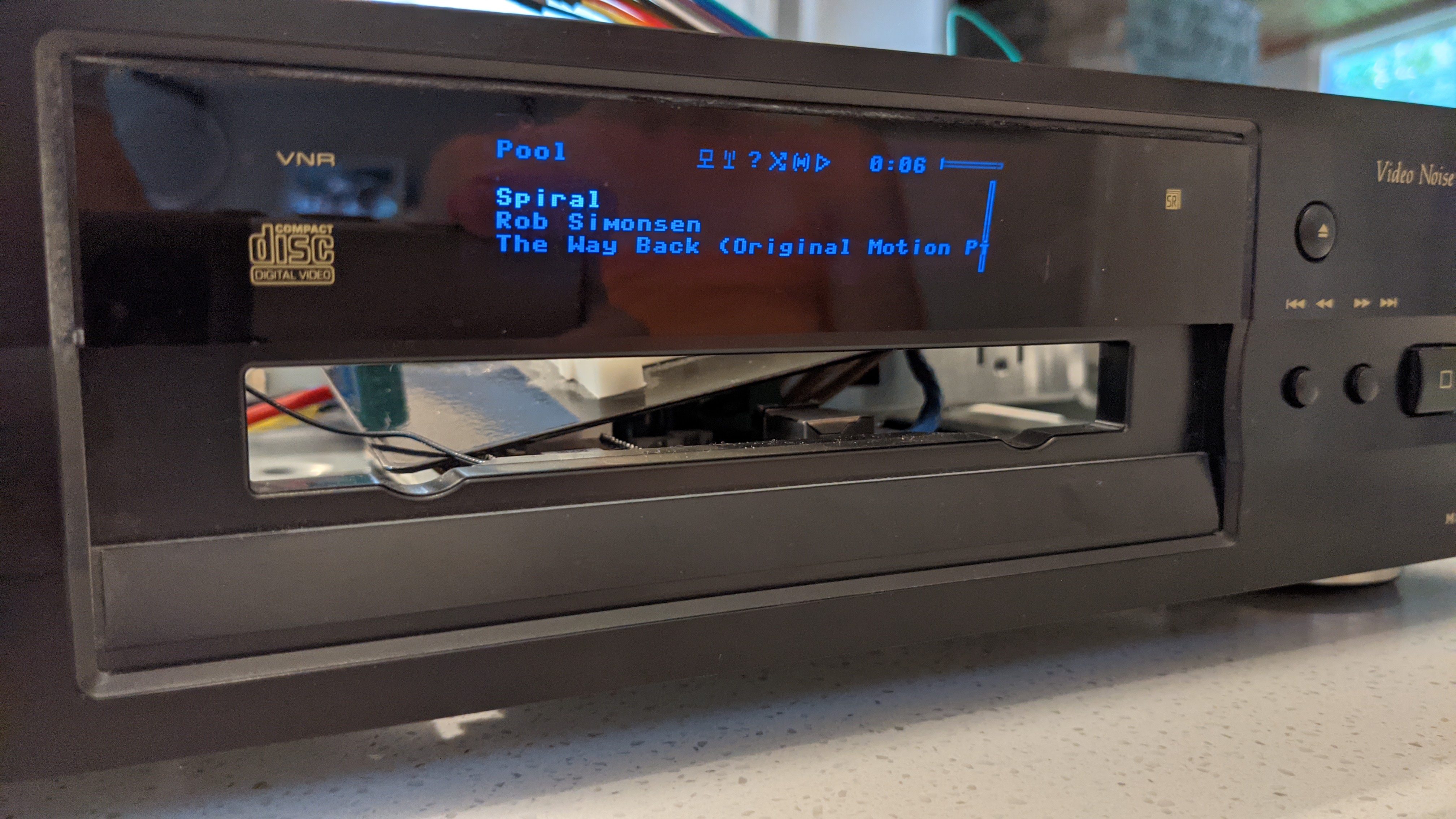
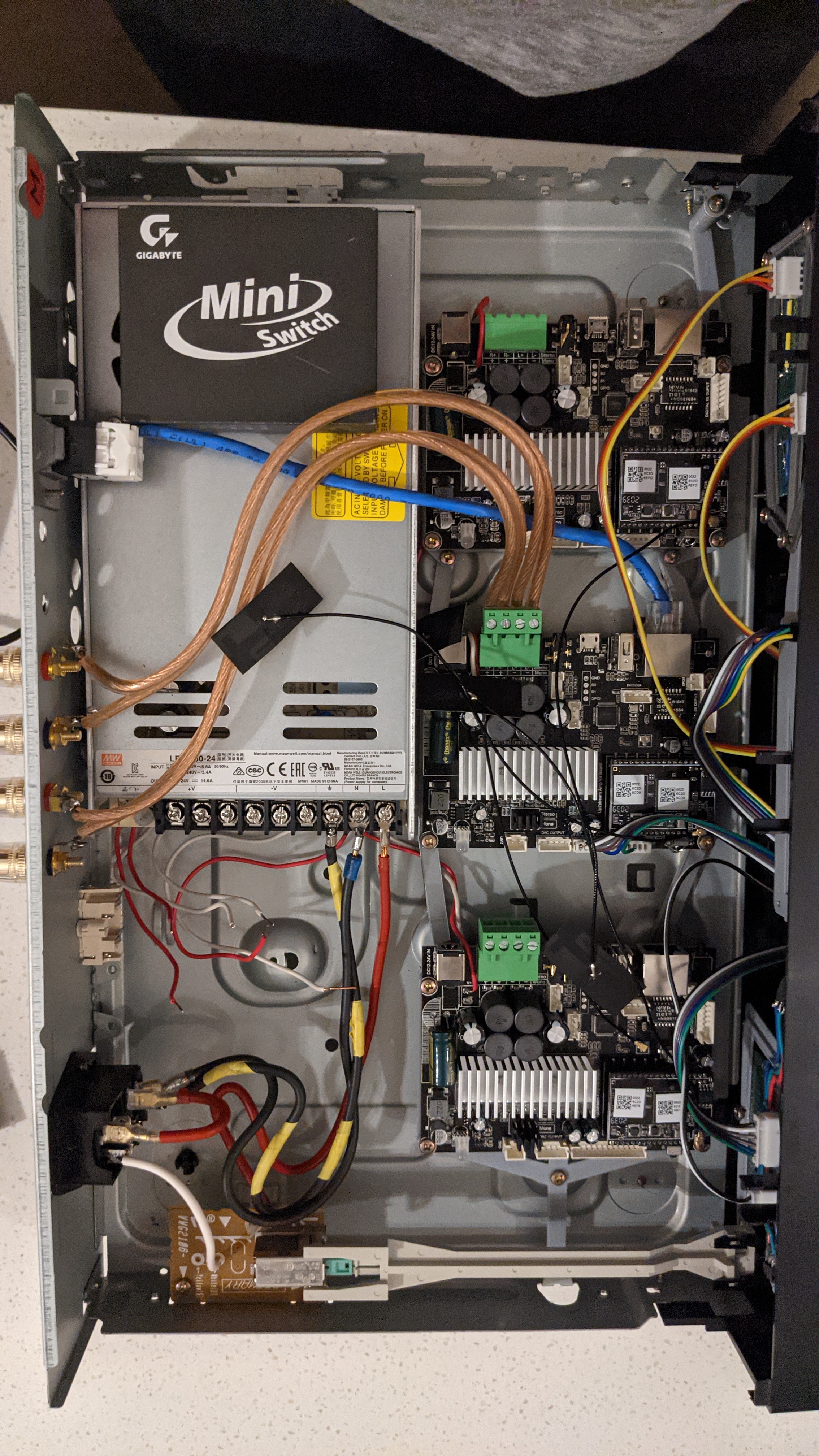
I have three v4 boards, which I’m building a multiroom amplifier, centrally controlled by a pair of raspberry picos, all inside an old DVD player case.
Here’s a couple of progress pictures;
However, I’ve hit a problem, which is likely of my own doing.
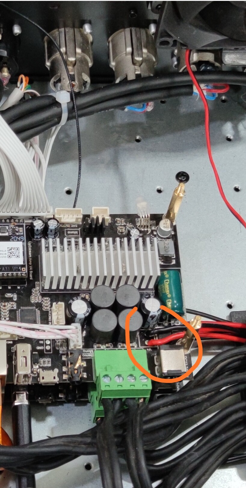
I soldered a +ve and -ve connection to the exposed solder pads on the top side of the board next to the power socket and speaker connector. I struggled to have the solder meld to the pad to connect the wire. I fear I used too much heat and damaged nearby components on 2 of the 3 boards (as 1 still works 100% fine)
The two that don’t “behave” see the following symptoms;
- When powered by 12-24 volt plug or solder pads, the LED will blink for a second or two before permanently off
- However, when powered by the serial connection power up
- LED blinks correctly
- Connect to wifi
- Allows changes to selected source with the button or Andriod App
- No audio from the speakers (I would expect this without enough power)
The component closest to the solder pad was the SK1010 “Rectifier”, looking at the data sheet (https://www.mouser.ca/datasheet/2/258/SK102_SK1010_HSMC_-2492222.pdf) I see max
High temp soldering 260oC for 10sec, and there’s a good chance I exceeded that trying to meld solder with the ground pad (I assume the heat was dissipating throughout the heat sink!!!)
Does this sound like my issue?
Anyone any thoughts? Any test I could try to prove this is the problem?
Hi,
I am sure the Schottky diode is OK than this diode is on the board mainly used for polarity reversal. The heat wouldn’t destroy the diode so easy
I have also my V4 boards powered through soldered cables without problems. The soldering points are the same as the power connector, so if the board does different things when used the connector and if used the soldered cables you should check if the cables are soldered properly and on the pictures it seams the cables are very tiny.
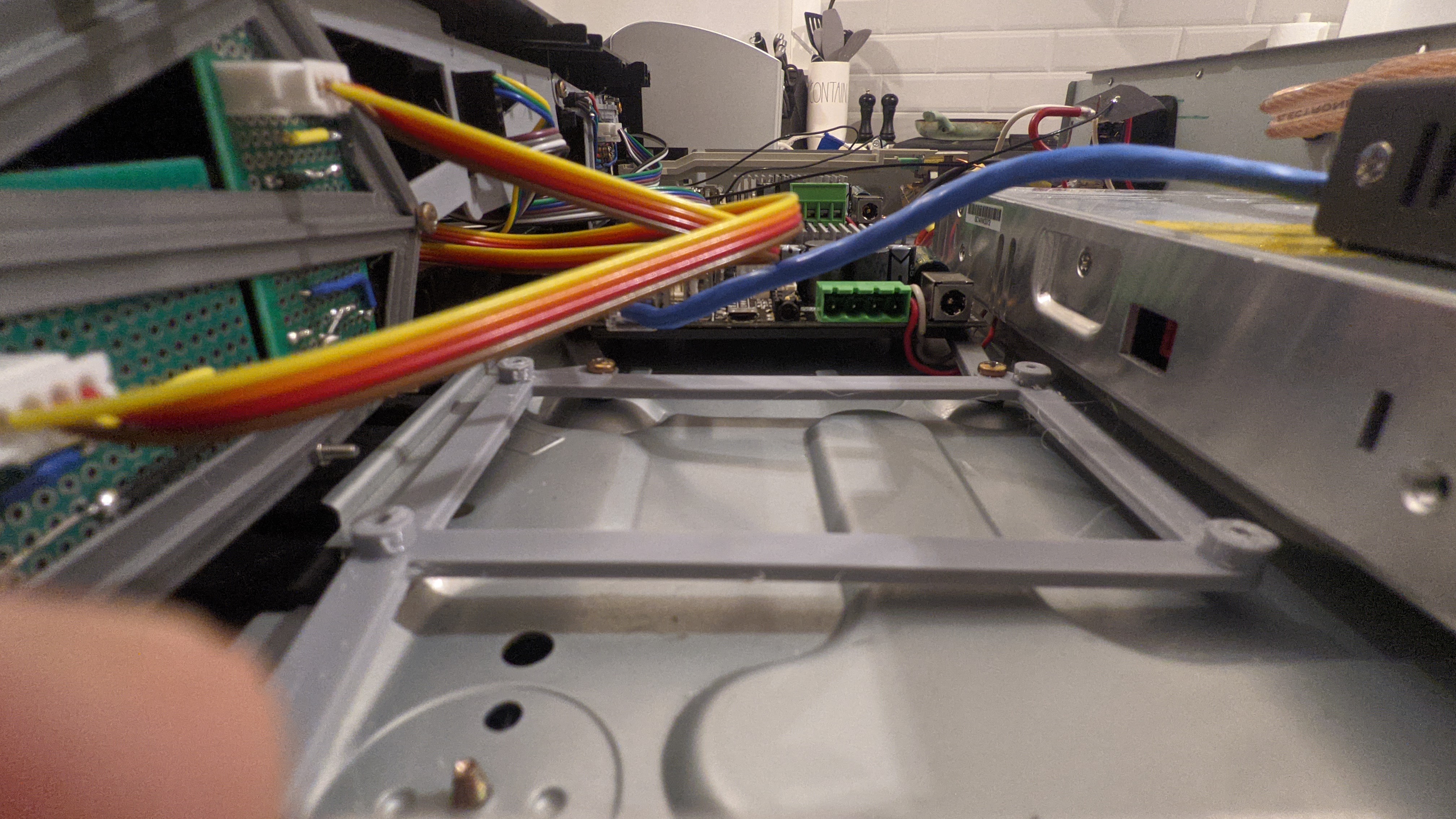
But one thing, are you 100% sure that the board doesn’t touch the metal shell of the DVD case on bottom? Some of the solderings on the bottom of the board are longer, if they Tuch the case she’ll it can destroy the board without problems.
Thanks Thomas.
What you can’t tell from the picture is that the boards are screwed onto 3d printed mounts that are raising the boards at least 10mm from the metal case.
As soon as they didn’t power up correctly i removed from the chassis and any further troubleshooting was done powering the board with a jack plug.
Given the boards are working when powered by low voltage, I assume the issue is with turning the high voltage to low. Are there any suggestions where I could place my meter to help identify the problem part?
Here’s another thought… While I’ve been building this unit over the last few months, I’ve been just powering the board via the TX,RX,GND,3V3 pins. The board that is still working is new last week, and hasn’t been used. I wouldn’t have thought a component could fail from under voltage or powered from the wrong side, could it?
Thanks.
New development!
While not fixed, if I power the board with power jack 12v at the same time as power the 3v3 pin the board appears to be fully working including sound out the speakers.
I’m able to send the API calls (over serial), and the amp responds an actions the requests.
Leading me to believe the issue is likely to do with the component that converts 12+v into 3.3. I’ll look around the board, unless someone can point me in the right direction?
When you only have the main power connected and it is not working, have you measured the voltage of the main power ?
Thanks for your suggestion.
When I was testing, I tried using both a 12v power pack, and the variable PSU in the images (which I ran around 22v).
If I use either of those power supplies on the “working” 3rd board everything is fine.