Hack Bang & Olufsen Beolab 2500 (6201) with mini v3

Hi there

Here is my latest project.

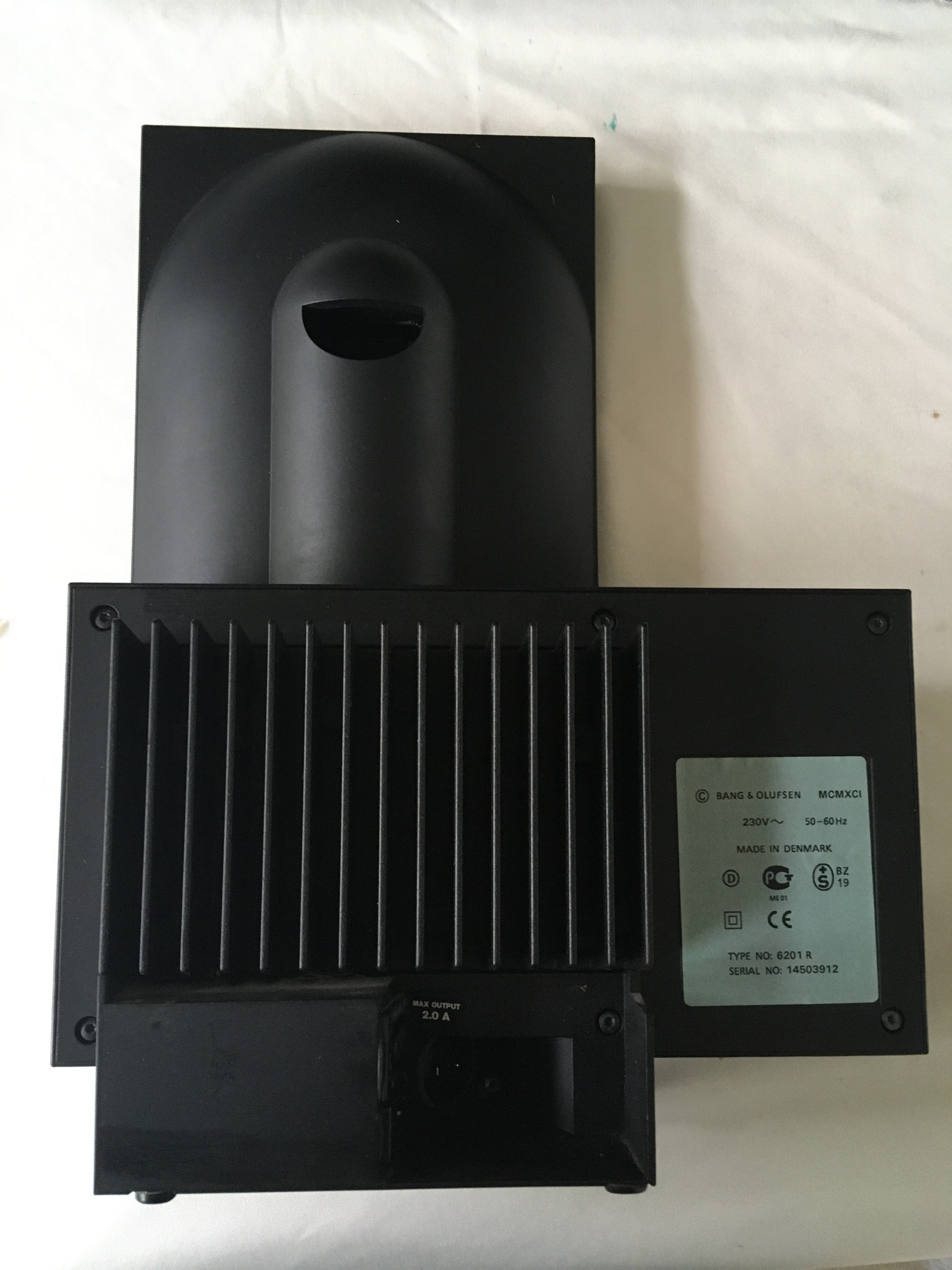
I acquired a pair of active speakers from a Beolab 2500 (the speakers are rated 6201) from the famous Bang & Olufsen brand.


For those who have already read other of my posts, I like to use DIY modules from the Arylic brand (www.arylic.com). So my ambition is to turn this pair of speakers into multiroom speakers!

These speakers still have about twenty years, the internal foam decomposes as soon as you touch it. I removed bit by bit to change it.


Uploading: IMG_0023.JPG


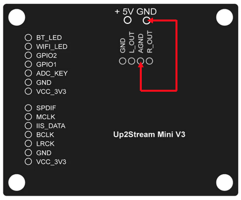
Wanting to keep the original look, I choose to integrate an up2stream mini v3 (Wifi Audio Receiver with Multi zone Control-Arylic.com) more compact than the pro version but with fewer connectors. I still add the DAC module to enjoy better sound quality and an SPDIF input to connect sources other than wifi or bluetooth. The speakers being active, I didn’t need to put an amp inside.

I was able to realize that if I just sent a source to the powered cabinets and well
nothing happened!

So I contacted the support of the brand to understand how to use these speakers with another amp / streamer and they kindly replied that it was not possible.

Ha truly? Really ?

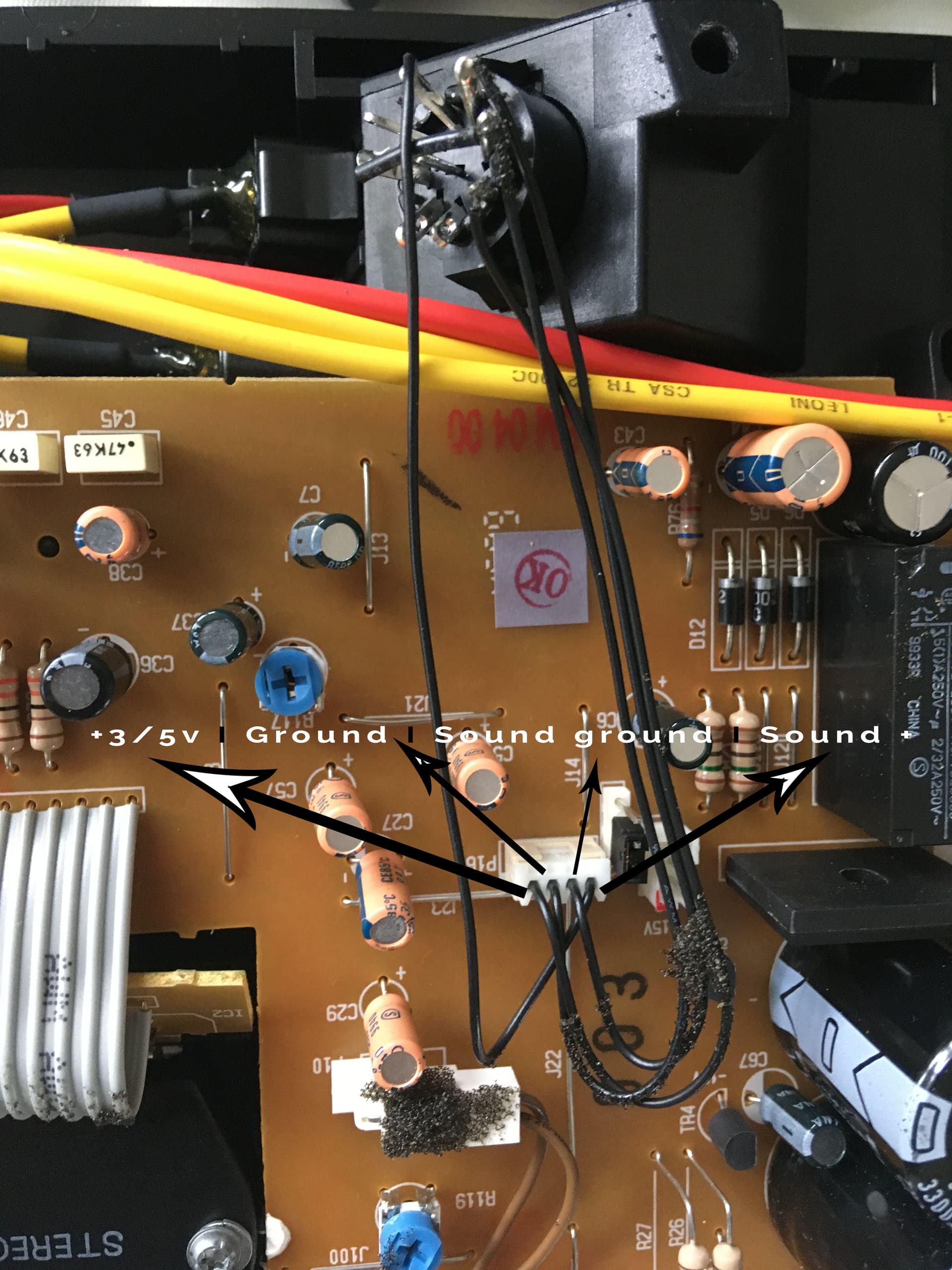
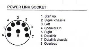
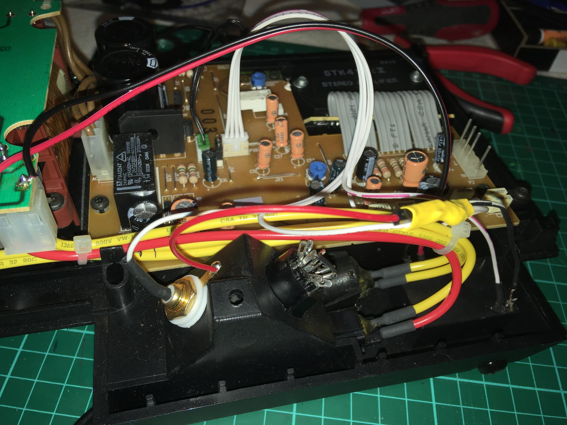
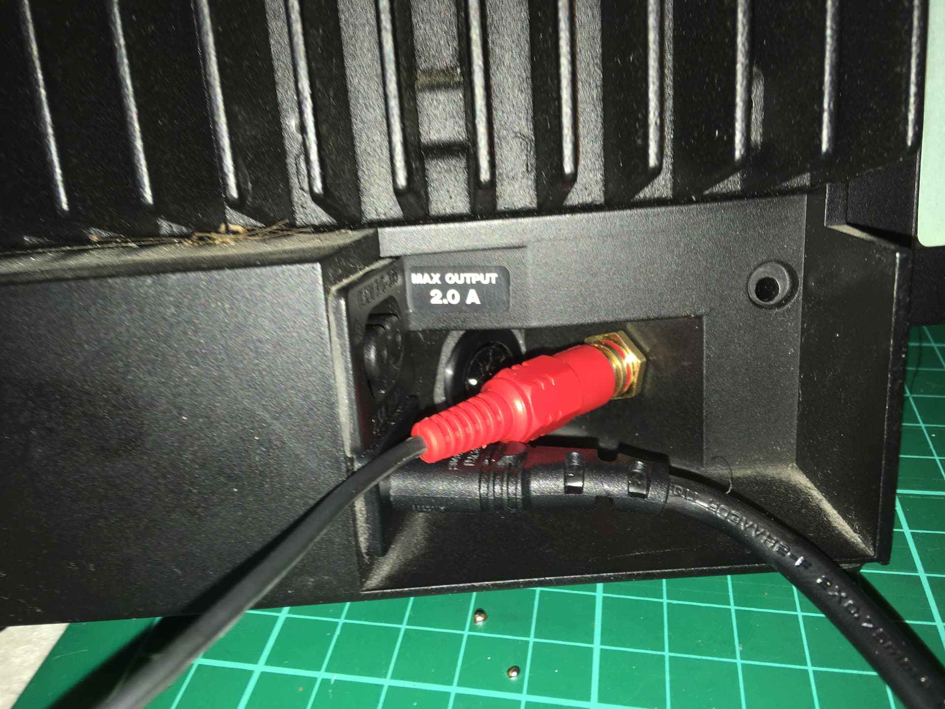
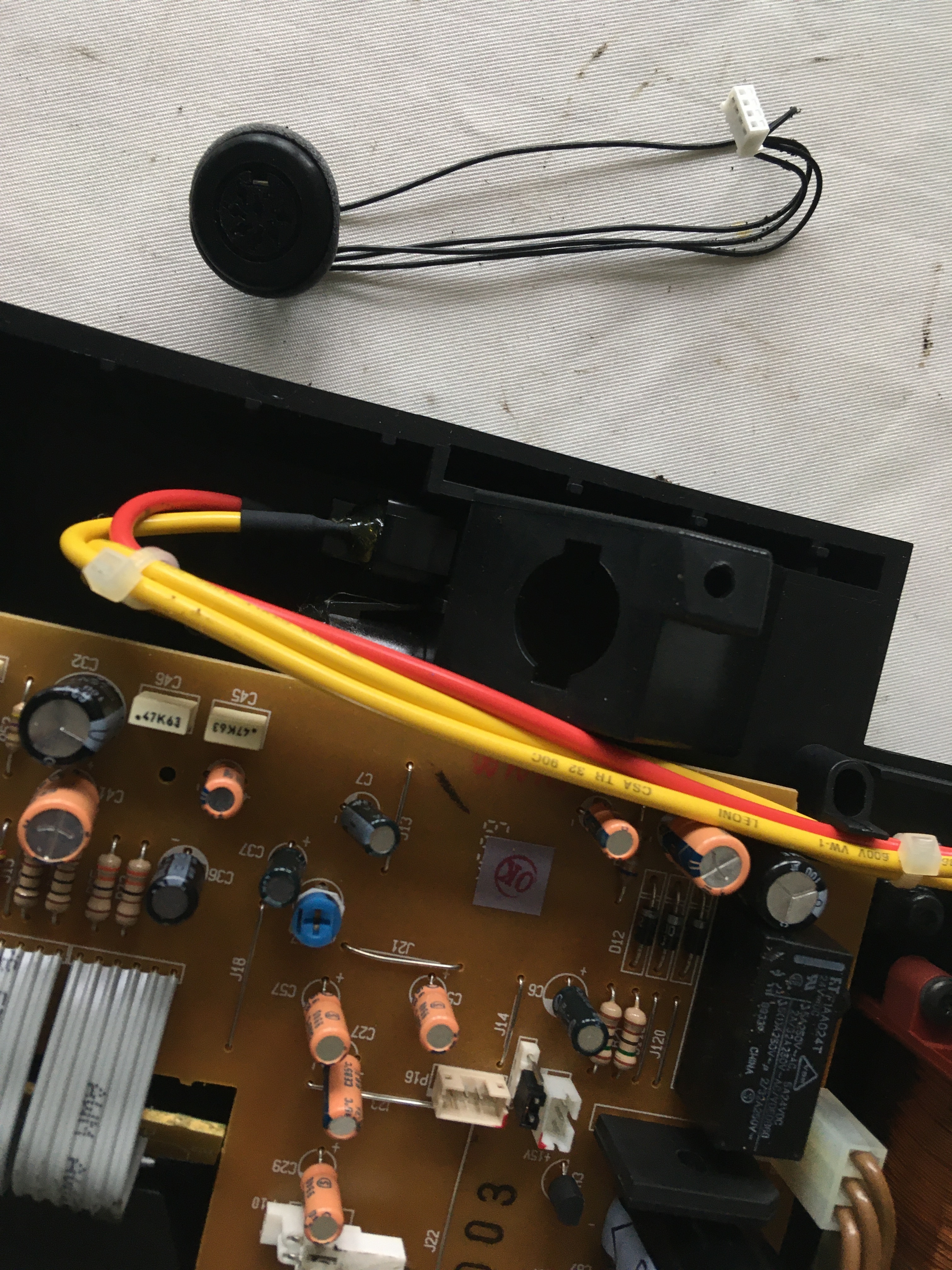
I started searching the internet and learned that these smart guys had “hidden” a trick in their amplification board. With their cable connected from their amp, in addition to the beep, a signal of about 5v is sent which “turns on” the amp.

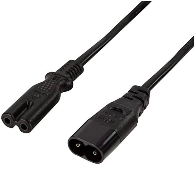
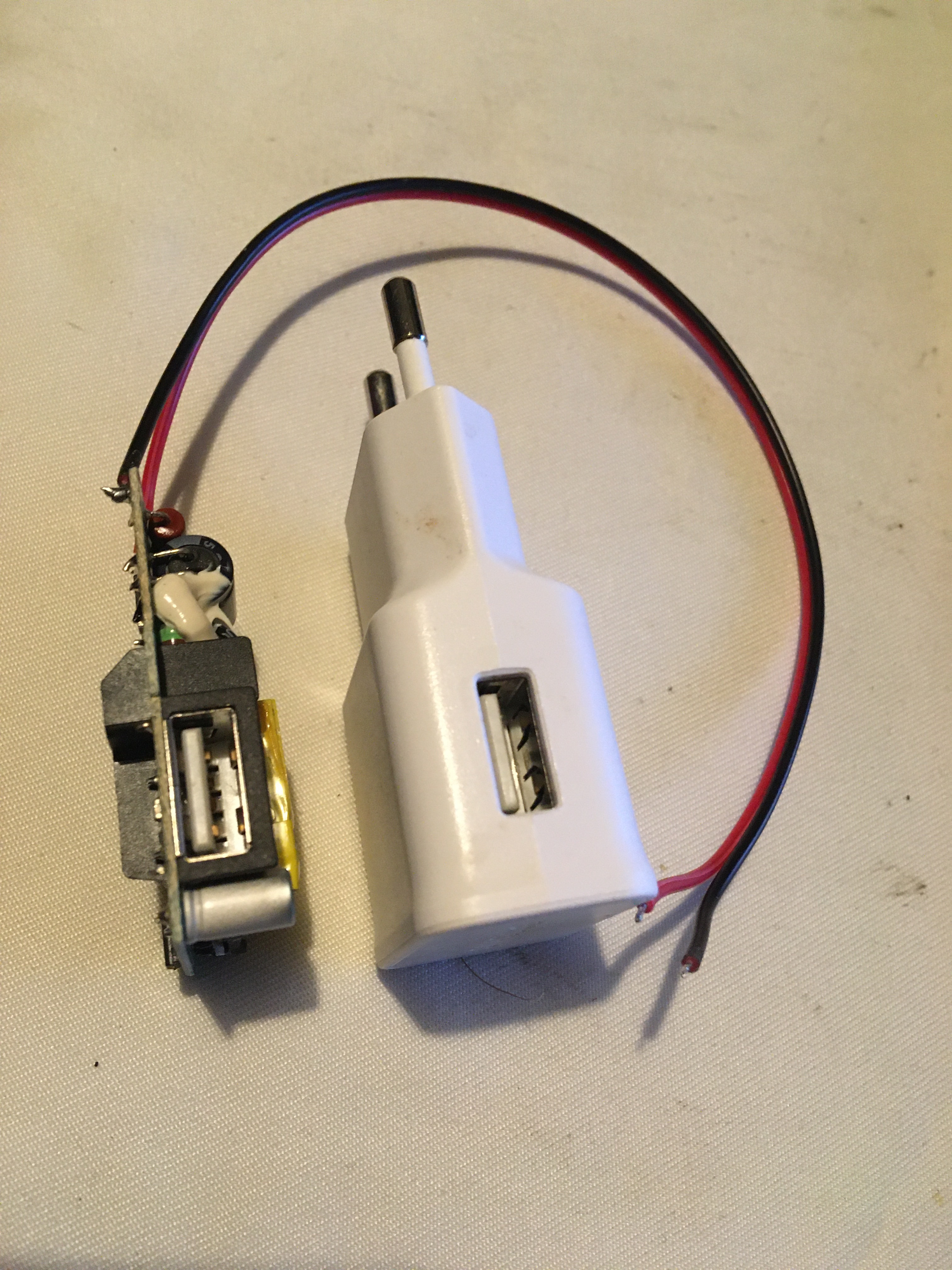
After further research I found a modified cable with a usb plug! Great !! Except the price, 37.5€
 for a simple cable
 hum. I have usb cable, chargers
 let’s tinker!

Ho but, I think about it, the up2stream mini v3 also feeds in 5v 1a


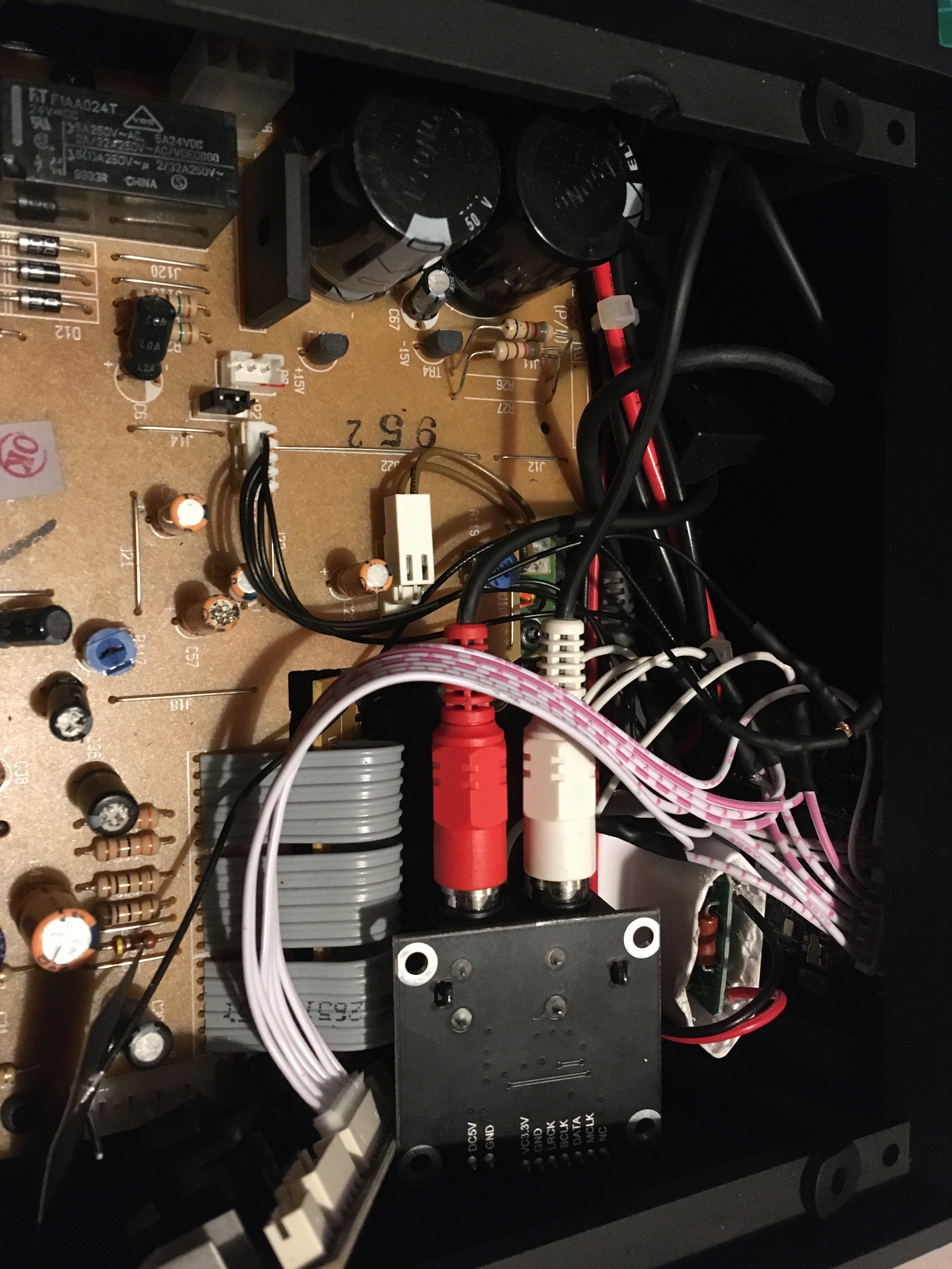
After some quibbling and a first test, the cabinet made a big BUZZZZ, horrible. I messed around a bit and luckily the mini v3 board can output 3.3v, so I used that option to power the amp and there, miraculously, no more Buzz! Is it because I’m only sending 3.3v and not 5v or going through the Arylic board removes the ground loop? I do not know.

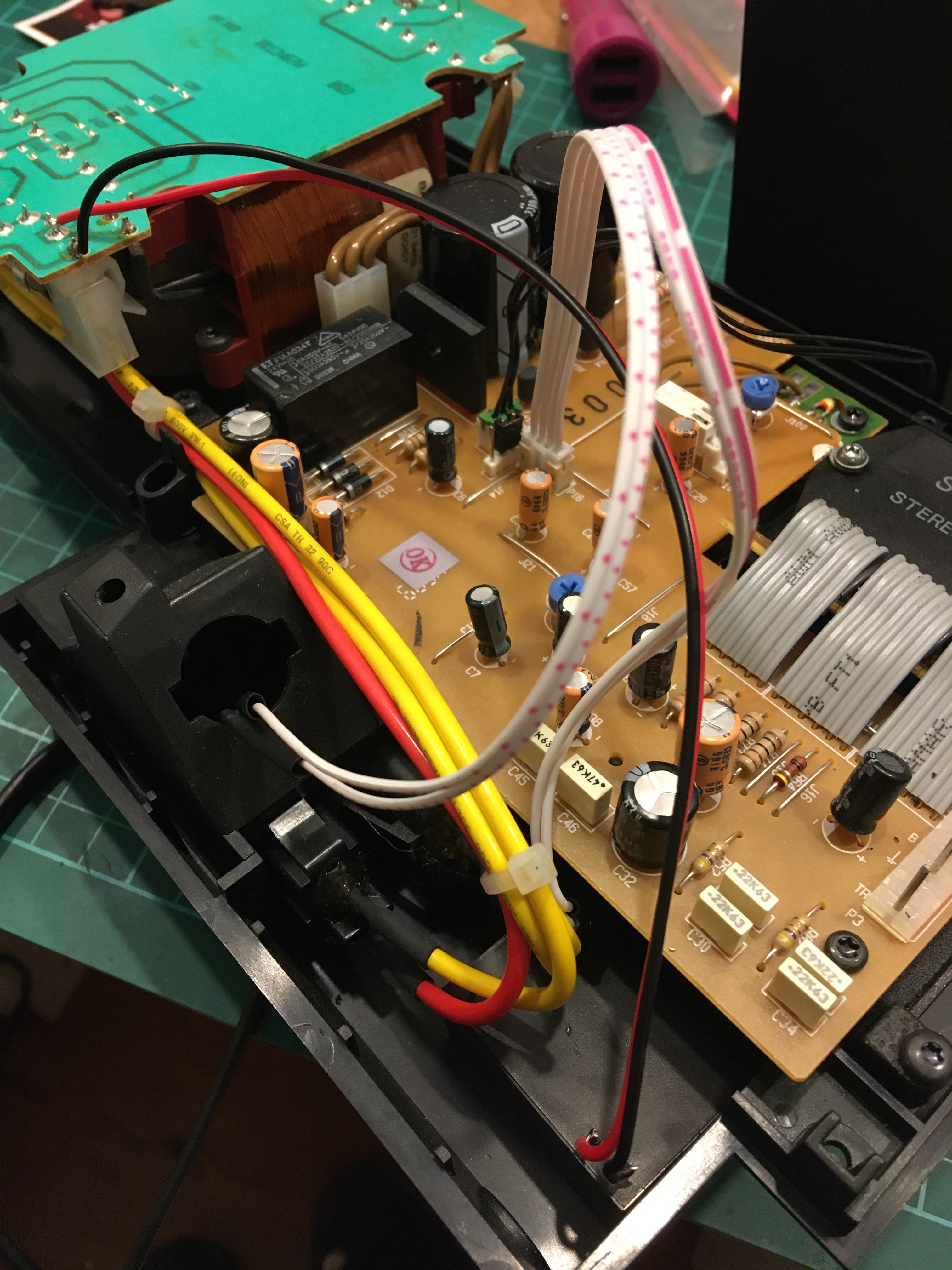
A little cutting, welding and foam and we can close the beast.

I tackled the second cabinet. Based on my first experience, I decided to buy a small 220v to 3.3v transformer from AZ delivery. It is small and fits very well in the small space of the baffle. Unfortunately the first module no longer works after two or three ignitions. I test a second, it seems to work, I add the baffle and Horror 
 the big BUZZ is there again. Yet I feed in 3.3v. I test with another arylic mini v3 card and there! That works ! But it’s not great for a real stereo.

But hey, I can’t see myself putting a second card just to get the 3v out to the amp
 So I’m looking for another solution for the right baffle or like isolating the cable or something else to no longer have a ground loop.But hey, I can’t see myself putting a second card just to get the 3v out to the amp
 So I’m looking for another solution for the right baffle or like isolating the cable or something else to no longer have a ground loop.

If ever a good soul has the solution, I’m all ears!

1 Like

@Tot - Congratulations you came this far!

I checked the BeoLab 2500 and noticed it only has the PowerLink inputs to get an audio signal into its integrated amplifier. And yes Powerlink works with a trigger signal of 5v to get the amplifier from Off (Stand-by) to On.

Here’s some question to better understand what you did:

I am very curious how exactly you made the connection for the audio signal.

  • Did you connected the DAC extension board via flat cable to the Mini? (because I think I see that the Mini is connected via flat cable to the 8-pin DIN connector, on picture 5)
  • Are the RCA plugs on the DAC extension board Audio Out? Where are they connected to at the BeoLab 2500 side?

For switching the auto stand-by from Off to On, the 5 volt trigger signal is needed.

  • How exactly did you do that? I do not have a clear picture about the 5 vs 3.3 volt explanation.
  • Picture 4 shows a power adapter. Did you use that for powering the Mini?

So please try to respond to the questions, and give some more explanation how exactly you did things. I would suggest to add a kind of drawing that shows what you used and how you connected things.

Nice project, and willing to help!

1 Like

Hi!
Thanks for your message!

To answer your question, yes I connect the DAC extension board via flat cable to the mini to be an audio OUT. I connected the RCA cable on one side to the DAC and on the other side i cut the connector to connect the wires in place of the PowerLink.
For now the RCA cable go throw the hole where the PowerLink were. But when i’ll cut the ground loop i’ll put an RCA connector so i just put a rca cable for the right channel between the speakers.

Here is a detail about the connection and alimentation:

About the switching the auto stand-by Off to On, a signal between 2,5v and 5v is needed.
The internal transformer can return 220v in order to connect the two speakers in parallel.

For a speaker I bridged the 220v from there to my little 5v1a usb transformer (photo 4) which directly powers the mini v3 via usb. For the second I bridged from the transformer to my 220v-3.3v transformer as you can see in the last photo of my first post.

I hope it’s more understandable.
If not, tell me and i’ll try to make a drawing or another picture.

:wink:

Thanks @Tot, for your further explanation and photo’s!
This clarifies a lot more.

There is one thing I would like to understand better. It is about the ‘switching of the Auto stand-by’ from OFF to ON. Like you mentioned, there is a 5 volt signal needed, to enable Auto stand-by to switch ON. The 8-pin PowerLink connector needs the 5 volt on pin 4 to make the switching (see picture below).

But how exactly does that work?

  1. The PowerLink connector gets 5v continuously, and an incoming audio signal is the trigger?
  2. The PowerLink connector gets 5v as a short trigger (e.g. fraction of a second), caused by incoming audio?
  3. Or 
 ?

Can you share how this works/how you made it work?
I am especially interested if your configuration can switch ON and OFF power when a music stream starts or ends (so automatically).

Screenshot 2022-12-14 13.33.10

Hi KolfMaker,

Sorry for the late answer!
I’ll try to answer your questions!

I don’t have the Bang and Olufsen amplifier Beolab 2500, only the speakers 6201 (whose amplified). So i guess that the amplifier send audio and the 5v at the same time and it’s trigger the speakers.

The picture you put is not the power link for the beolab 2500 but for another one.

As you can see on my first picture on my second post, there is only 4 wired linked on the power link socket. It’s because one cable is used for Left speaker and one cable is used for Right speaker.

I find a solution about my ground loop. You can see a wire between the V-(ground electric) and the ground for the sound: the result is magic!

About my configuration, i can switch on and off because the 3,3v transfo is after the 220v. So I put a switch on my cable so everything is feed or not.

The two speakers is wired with this:

Did I answer everything?

Thnx @Tot !

(1) So if I understand well, there is no automatic switching from Stand-by to On when sound starts playing. Right?

(2) About your ground loop:

The wire you mention, is that the short horizontal black wire in the 1st picture of your 2nd post?

(1) For my hacked system: no. But I read about a B&O device who automatically Stand-by after 15min if it does not detect an audio signal
 So i guess this is possible and i suppose that is what they use and it is commanded from the amplifier. Maybe a B&O owner can agree??
If you put the 3v from the audio source, it will do that (if your amplifier has this capacity) but in my case, all of my Arylic’s B&O stereo is On or Off with one switch because my up2stream mini v3 is integrated in the speaker.
(2) Yes absolutely! But i don’t use this connection 
 I’ll add pictures in a few days when i’ll be on holiday!

What is your project?

(1) Ok, that’s clear. I am looking for an idea how to build my own automatic audio-sensing and ON/Stand-by switching circuit. If I have something, it can be used for many different speaker projects. So if you come across something like that, lets me know.

(2) Yes, please let me know what connection you use and where you put the wire to solve the ground loop.

My projects are many different speaker projects. For instance, I am now working on transforming passive speakers into active speakers, combined with Up2Stream Mini. But I prefer to make them auto sense and switch on an audio signal. So they will be in Stand-by when not used, and switch to ON automatically when I start a music stream.

(1) If you want to reuse Bang & Olufsen speakers i think you can “only” modify their power link cable from one side and sending 3v from the mini v3 and the sound trough the cable. So the speakers will pass from Standy to On when the mini v3 is On? I haven’t studied the way they are doing that for now


(2) Here is a photo. In fact I wired the GND between them. The ground from the transformer 220V-3.3v and the ground from the audio signal. It was “that simple”.


And this is the back of the right speaker when all is done.

@Tot

Thanks for sharing the info & pictures, very much appreciated!

Buzz solving
So if I understand right, you made a connection between GND/- of the 5 volt power to the Mini, and the GND of the Audio signal (OUT), to solve the buzz.
Is this like the connections in the picture below?

Schermafbeelding 2022-12-30 om 15.33.34

Hi!
In fact, the ground loop wasn’t on the piece with the mini v3 because the ground go throw the board and to the audio Channel. The ground loop was on the second speakers where i don’t put a mini but only à transfo 220-3.3v and a rca in. That’s on this speakers who a connect the ground from the audio in (coming from the mini) for the right Channel and the v-(ground) from the transfo. So it connect the ground from the two speakers!
I hope it’s more understandable like this :wink:

I wish you and all an happy new year!