What do OUT CTRL and AMP MUTE and the others really do?
What I want is to get a signal when the unit is via the remote switched into standby to switch an external relais.
The documentation doesn’t detail (and in the video on youtube), for me the explanation is outdated, as the AM Mute is not described.
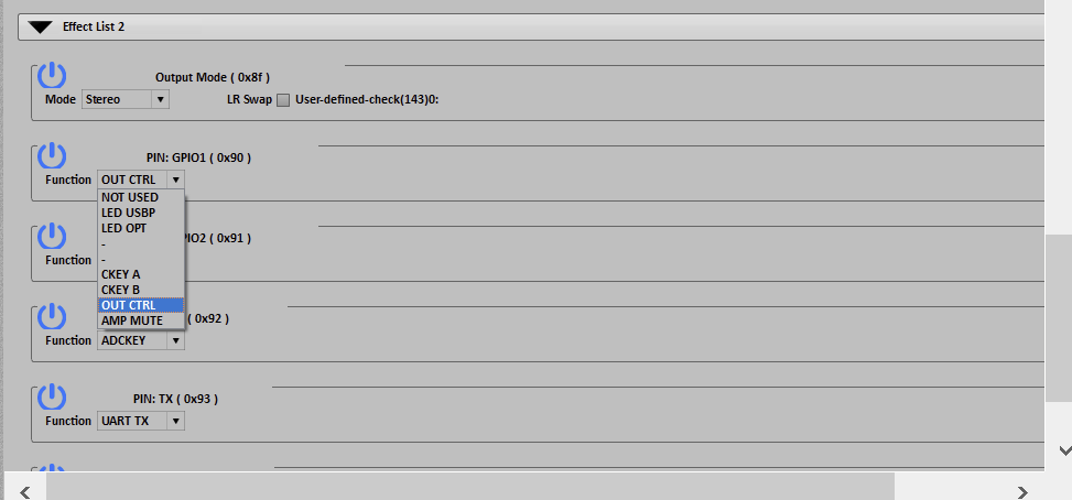
What I tried now is measuring the voltages on GPIO 1 &2 and settting them to either OUT CTRL or AMP MUTE, but the voltage is always the same it seems.
Please elaborate this would be highly appreciated
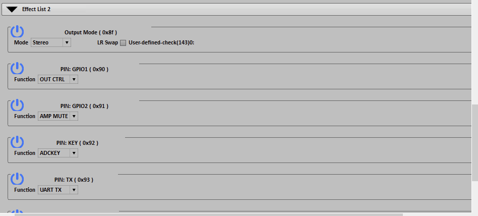
Hi, normally, when configured the pin as OUT CTRL, it would output high when detected audio input, and output low when not detected audio for 60 seconds.
For some reason, GPIO settings in ACP Workbench do not react on just setting the output to OUT CTRL until you upload the configuration to flash. Then it works.
Another issue is if You set GPIO 01 to OUT CTRL it works, but if you also save GPIO 02 to OUT CTRL, then GPIO 01 stops working? I think that is an error.
What should AMP MUTE do, it does not change anything?
I am writing about AMP v4, not sure about other boards.
The device only supports to set one PIN as OUTCTRL, I’m not sure why you need two, you can just connect them together if you want to use two.
AMP MUTE is designed to work as input, for some models which have integrated amplifier, it could be used to mute the on board amplifier with external voltage level, you could pull this PIN to GND to mute.
By coincidence I just came across this post (it’s some time back, but anyhow). I am trying to work with GPIO and the OUT CTRL setting too.: I have just posted about it here.
So I understand that OUT CTRL can only be assigned once, which makes sense to me.
But I have also difficulty finding out how and where in ACPworkbench, to make the right settings.
Can you check my post and maybe comment on the questions there?