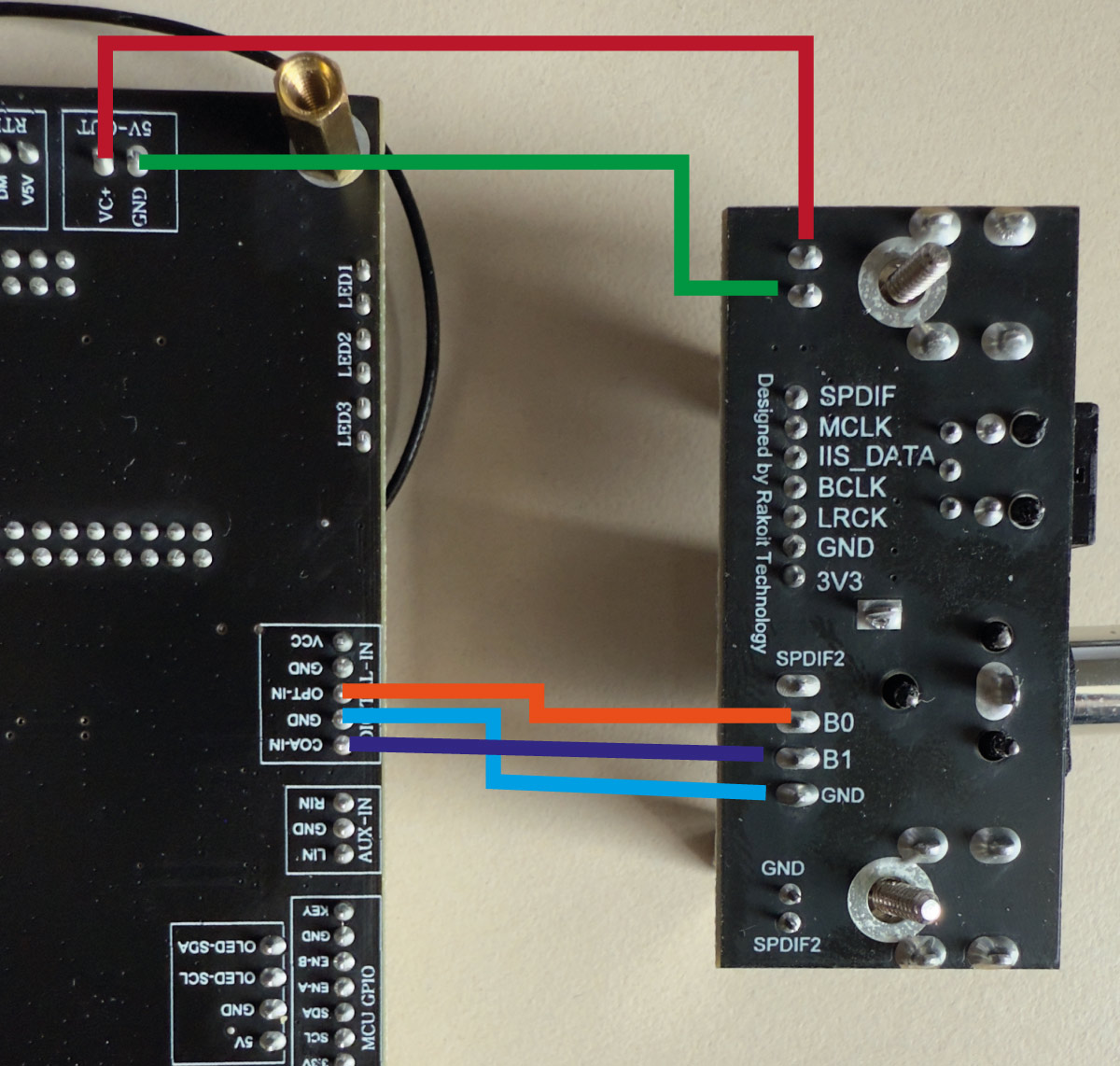
How to connect the SPDIF-Input board with the Up2Stream HD DAC board? On the Up2Stream HD is a Digital in with Digital-In with labels COA-IN, GND, OPT-IN. But on the SPDIF board only B0, B1, GND.
Is OPT-IB B0 or B1?
Beside the Digital in, there are also an VCC and additional GND. Its this VCC-In, or schould I connect the 5V-Out of Up2Stream HD with DC5V-In with In-board?
Hi.
The manual of the HD DAC section 4 states
In general, (TosLink) opt audio link (or coax) uses the SPDIF standard, the common pattern of digital consumer audio signals with all the information needed i.e. CLK, LCLK, Data.
As for the Vcc, it’s a 5v out intended to power the TosLink optical interface.
Good luck
N.
Sorry I misread your first post. IMHO, the SPDIF input board is not compatible with the HD DAC. (discontinued product…). .The HD DAc doesn’t handle I2S signals as input, so you can not use the I2S output connections of the SPDIF input board. Moreover, if I correctly remember for the other Aryllic’s board supporting the SPDIF input board, you have to use the Arylic’s ACP Workbench software to correctly define which digital inputs should be used. The ACP workbench doesn’t recognize the HD DAC as there is no USB i/O feature.
However looking at Up2Stream AMP 2.1 manual indications about how the SPDIF input borad can be connected, I can see that the SPDIF signal you need is the SPDIF2 pin, or the SPDIF.
The B1 and B0 are GPIO signals used to indicate to the board which of the coax or optical input board are in use. Not to be connected to either coax or opt inputs on the HD board. If I was you I would try using the SPDIF or the SPDIF2 pin, making sure the toslink connector is powered via your red and green wires, and play with the B0 B1 connected to either GND or VCC via a 1k resistor to get the proper digital intput set to the SPDIF pin.
Or you can wire the 2 connectors as indicated in tmy post you refer to.
If you give me a picture of the board view from the top I can further guide you for this solution as there may be some components to remove before doing so.
Good luck
N.
After reading your reply and the linked topic, in my original post, I came up with this idea. It seams that the digital inputs of the Up2Stream HD can be directly connected. What do you think?
yes, that’s the spirit of my earlier post. It should work. Your picture is much clearer than my sketch…
Looking at the attached view from the top, I conclude, I2S pins are not even connected to anything as it seems there is no I2<>/SPDIF conversion chip. it’s just for the sake of the pin-out compatibility with other boards via a Arylic’s ‘standard’ flat cable. (miniv3 / prov3).
Let me know about your success. (for other DIYers asking in the future).
N.
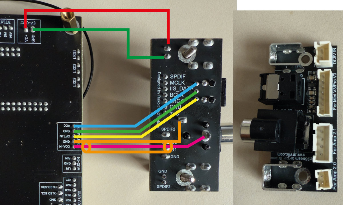
It’s not working. Do I need the extra connection with the 5V (red, green lines)? I tried all combinations:
with all connected (like illustrated)
disconnected (only blue, light green)
connected with 5V and disconnected blue and light green wire. In this case 3,3V is applied via the board.
Or is it a different problem? Software - I selected Optical in in app?
Hi, I don’t have the input board myself, so I can not test the different options you tried. But I would treat this at the component level i.e. the optical receiver as one standalone component and the coax connector as just a connector. almost as you did with the wiring you showed before. However, they might be some components to removed from the board, except the VCC decoupling capacitors and the impedance adaptation resistor (75Ohms) for the coax. Looking carefully at your drawing I’m pretty sure that the coax is wired reversed e.g. usually the pin at the rear is the signal and the pin at the front is the ground. This may not have any impact on the optical path but who knows… Then I would make sure the TORX (optical receiver) has the correct pinout according tho the datasheet. Usually they conform to JEITA Standard CP−1201, which would comply with your wiring. The 5V is mandatory for the optical receiver, it’s an active component (receiving diode+amp+trigger integrated) as well as the resistor mentioned previously. But it could be that the VCC next to the digital optical input on the board is switch on/off via a dedicated software setting. I would wire the TORX VCC directly to the main 5V. 9(Check with a multimeter if needed). I don’t have a TORX here to check, but if I can find some time I’ll check using the coax input on my board.
I’m not aware of any particular software settings, over the past 2 years after my purchase of an HD DAC, I could understand from my various research,that it’s a somehow ‘side’ product for Arylic that is not compatible with all the other DIY optional boards or software (ACP workbench). I have several Mini, ProV3, with additional optical output and so on, that work like a charm but limited to 44.1k/16bit in restitution.
I consider the HD DAC is more like an evaluation board, with very few guidelines from Arylic… In fact when I got it, the ap was not allowing Qobuz, they issued a patch especially for this afterwards, saying they had having hard time to get support from the linkplay side for this particular set up… some other products like the Cloudyx, Muzzo Cobblestone v1 and the Octavio streamers based on this linkplay A97 module have been discontinued too after some firmware updates that were not really satisfactory… (drop outs when playing 44.1k/16bit streams, for instance) and no further OTA updates from linkplay/Rakoit since 09/2023.
I know this doesn’t help… but there is not much more to do than trying ourselves some options…
Depending on your capabilities in removing SMD components, this should still be feasible…
Cheers
N.