Hi All.
I’ve just finished up my second 2.1 Amp “Boombox” and I thought I would share the result. This 2.1 speaker is my second attempt at building something along these lines using the Arylic 2.1 Amp module. It’s pretty much the only method I have come across (aside from the obsoleted Chromecast Audio) which allows you to build a proper ‘WiFi’ speaker. I actually started ages ago looking at the Mini and the Pro modules then decided that the functionality of having an inbuilt amp and sub output was probably the best approach (rather than looking to find a seperate amp solution).
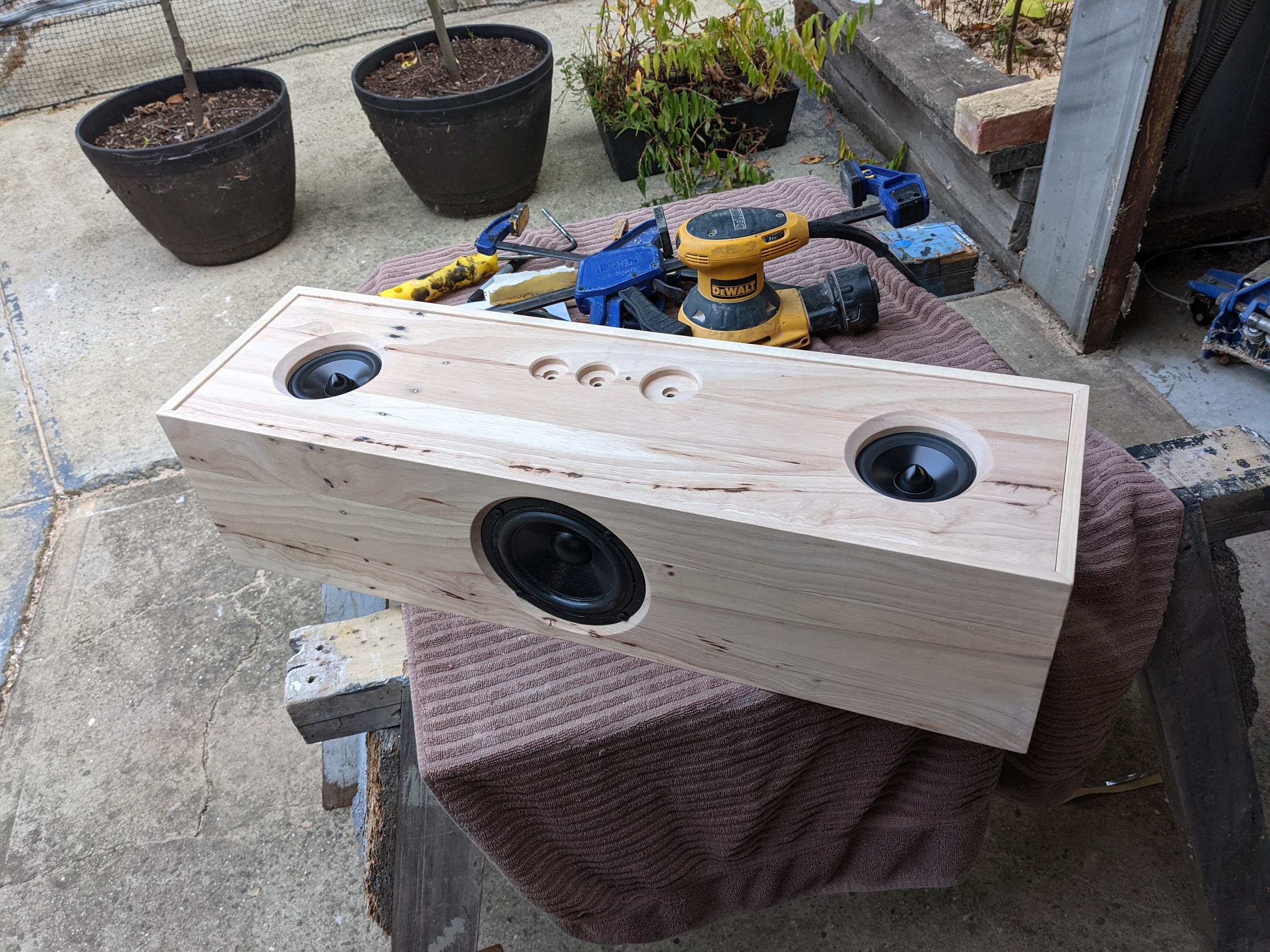
This uses 2 x Dayton RS100 full range drivers and 1 x DS135 woofer. All drivers are 8 ohm impedance purely because it is what I had available. It’s built entirely around the Arylic 2.1 Amp module with some add-on circuitry to suit my requirements.
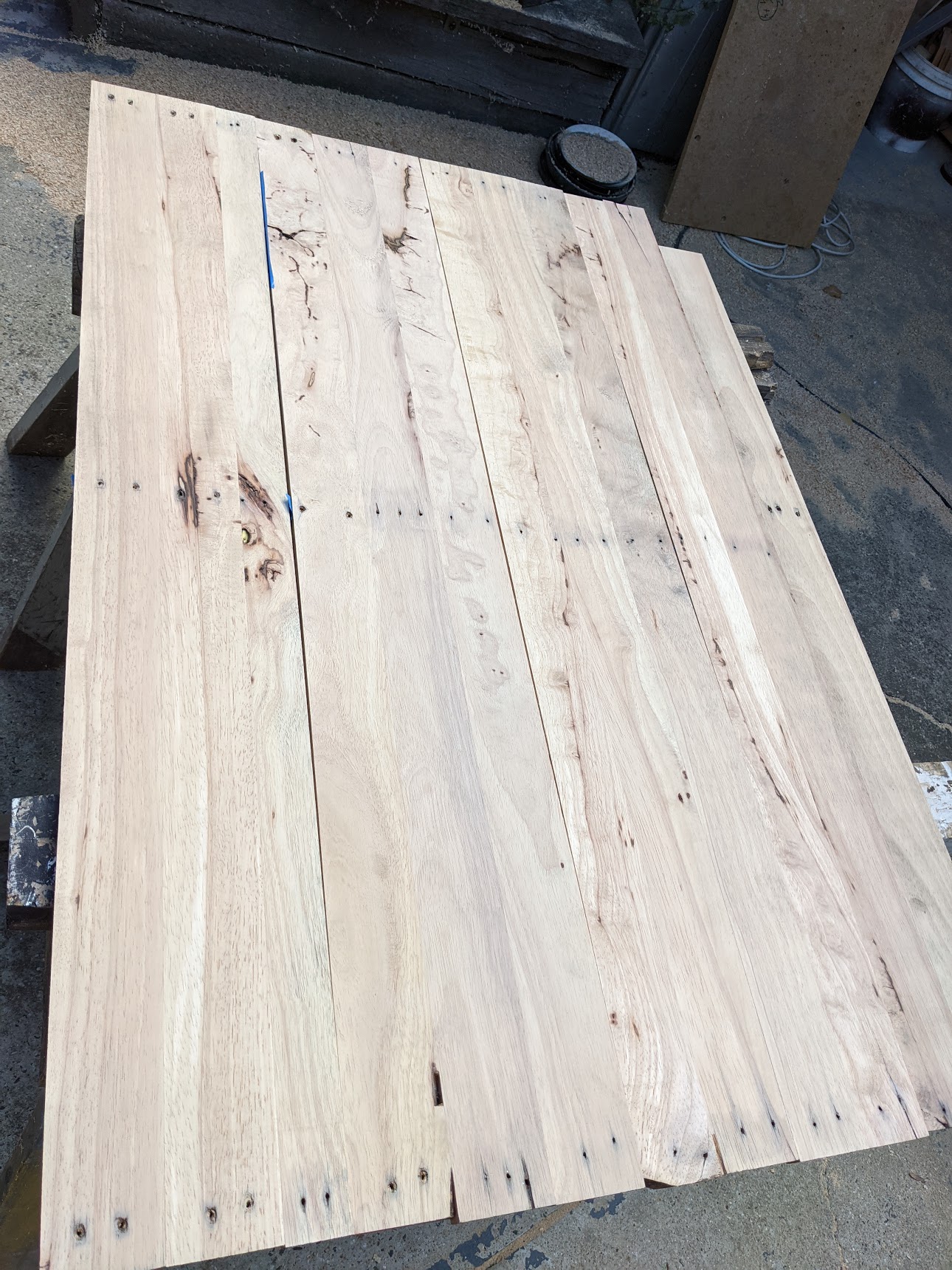
The enclosure is made out of 19mm MDF (I had a lot of scrap). The exterior is all made from an old hardwood pallet - base, top and sides are 10mm, while the front and back are approx. 16mm.
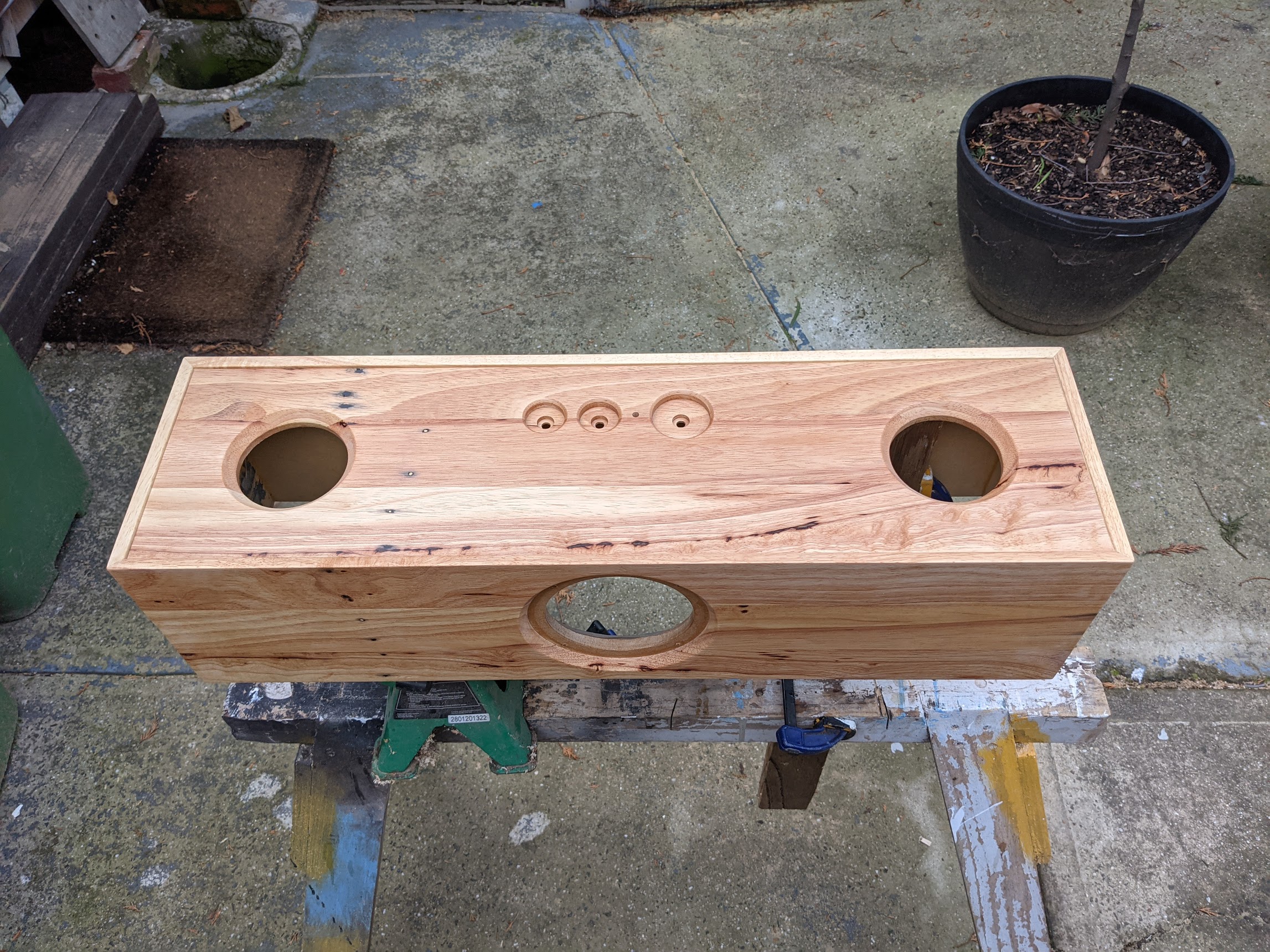
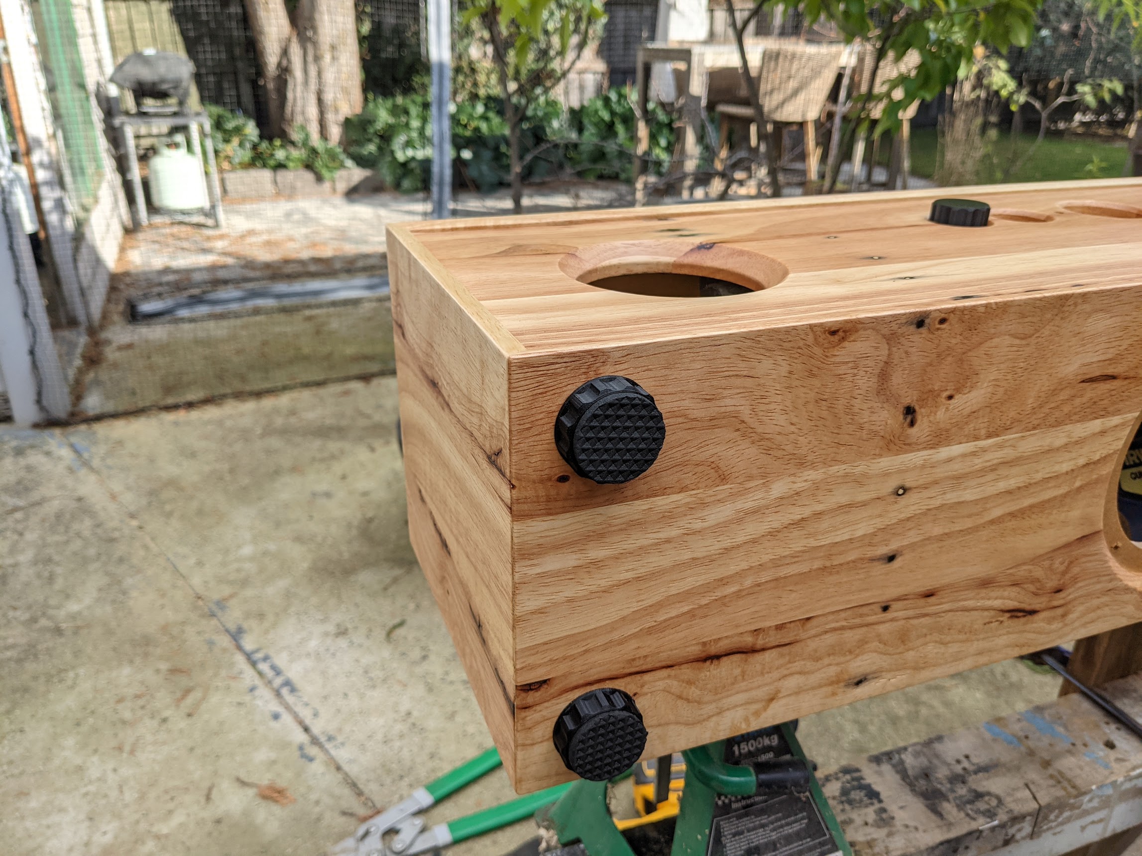
The front panel controls are bass/treble/volume knobs which have been 3D printed out of PLA. Single press of the bass knob = play/pause, single press of the treble knob = next, and single press of the volume knob = mode (same as the amp). I also have added one single RGB LED to indicate the chosen mode/status.
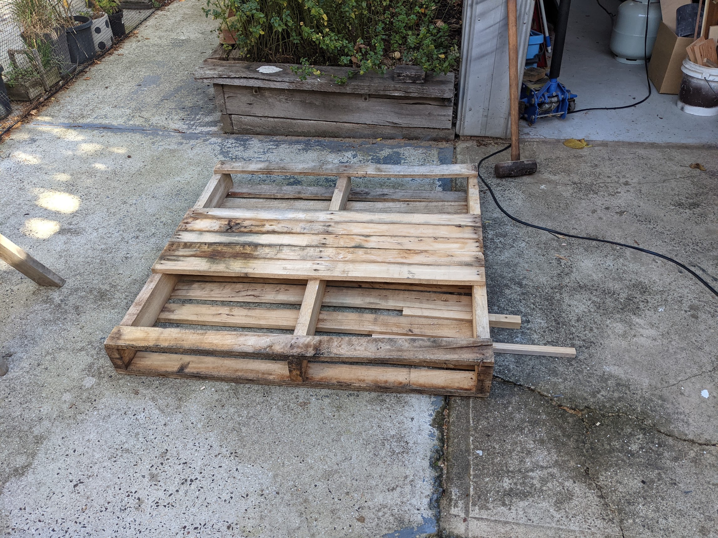
Here are some photos of the original pallet & preparation. I was not expecting the final result to come up as nicely as it did. It was a fair amount of work to trim these down, laminate them, thickness them, and fill the imperfections - but worth it I think:

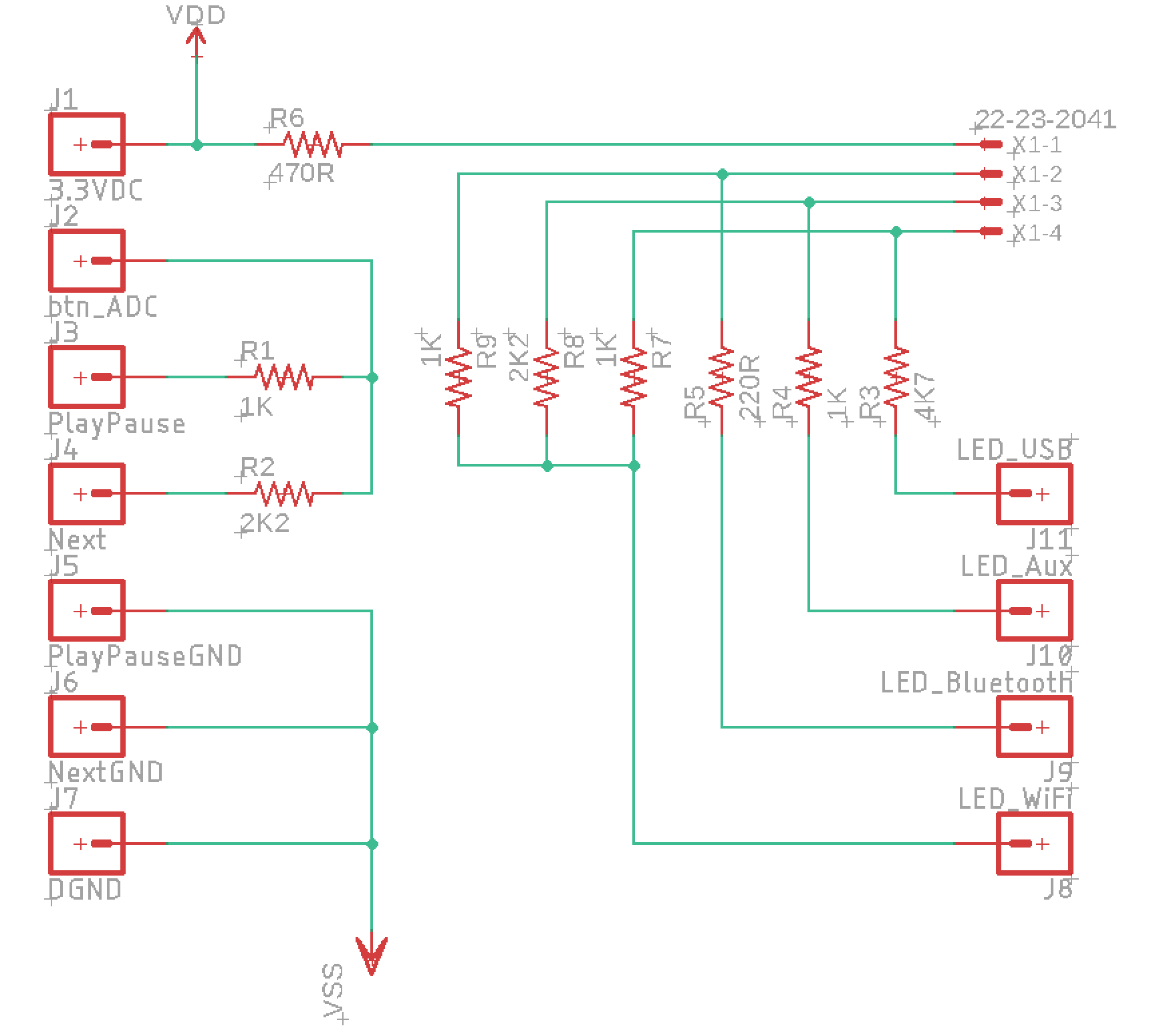
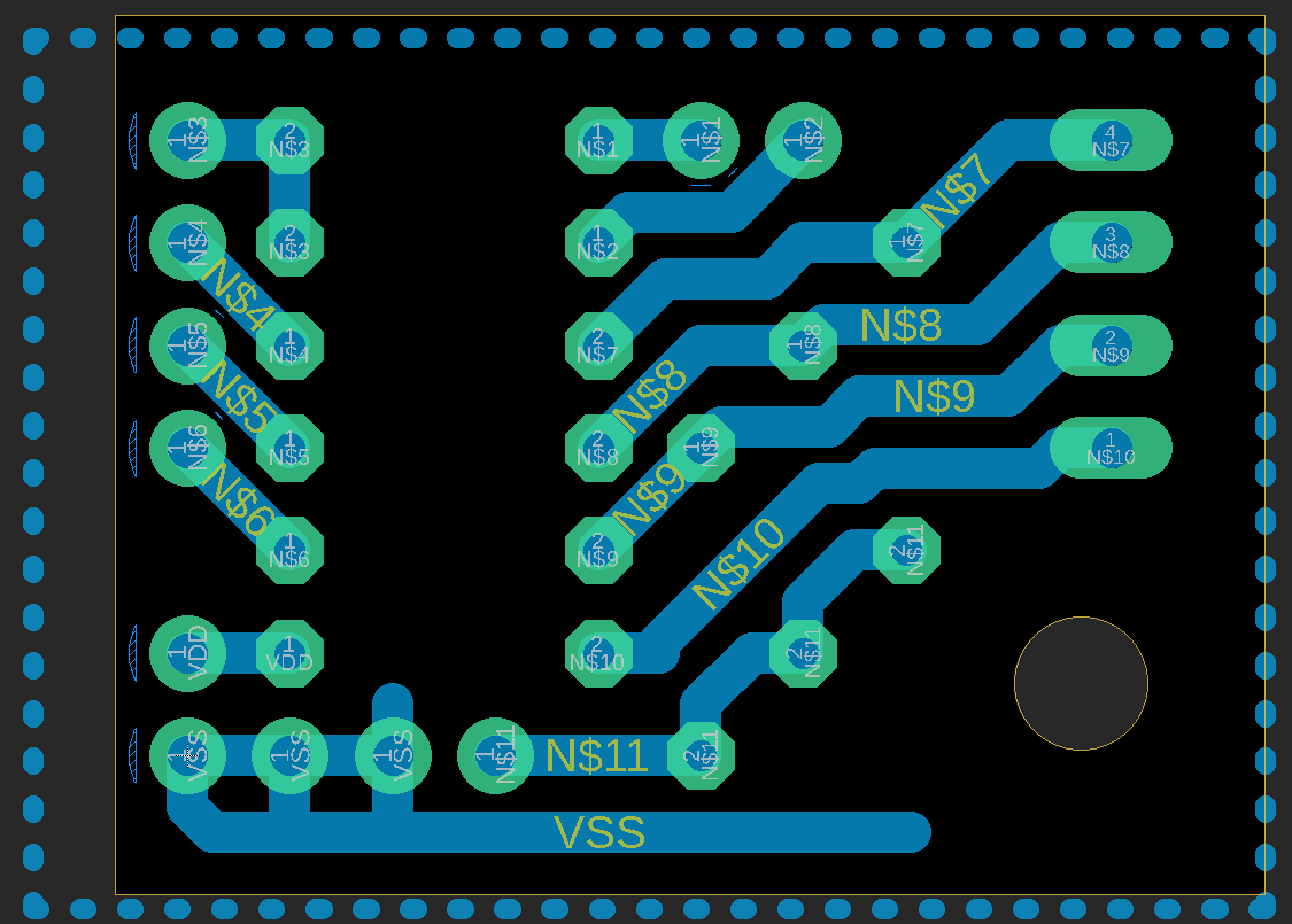
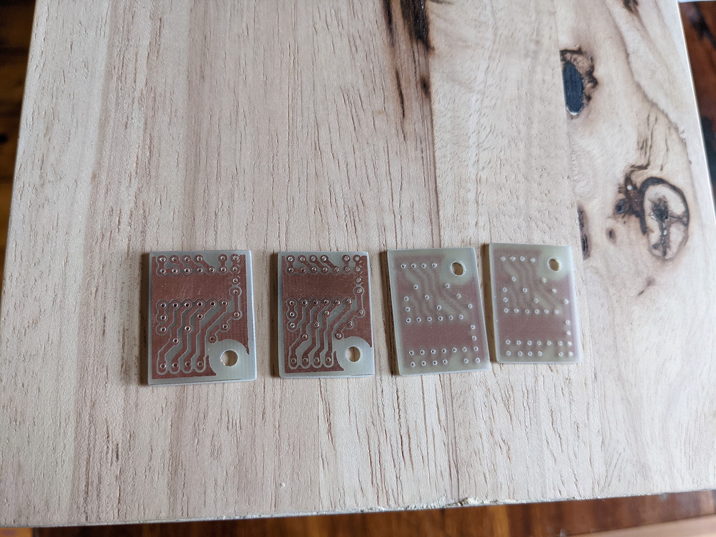
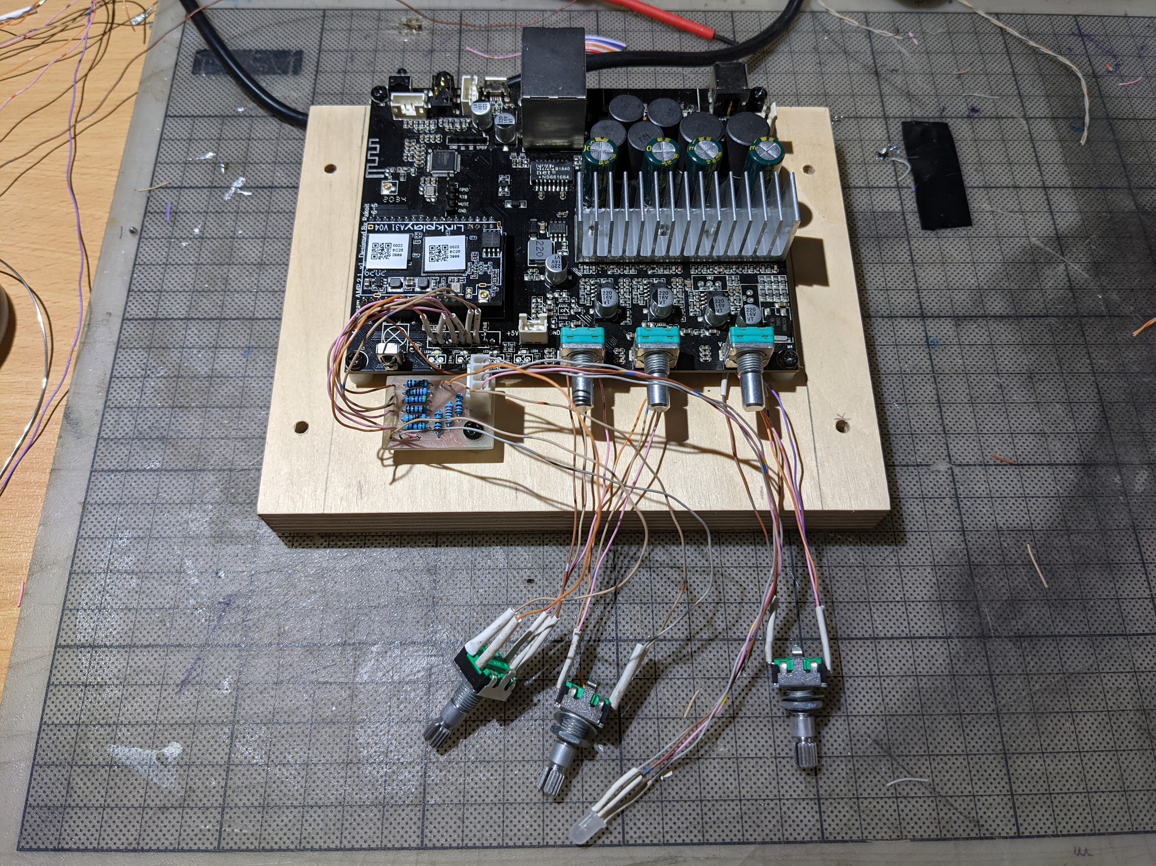
I made a PCB for the ADC resistors for play/pause and next buttons, also resistors to support an RGB LED instead of four individual LEDs. I also added new rotary encoders (in parallel with the existing - they are very hard to remove cleanly), soldered up the wiring for the ADC/LED PCB, and de-soldered the speaker terminals:
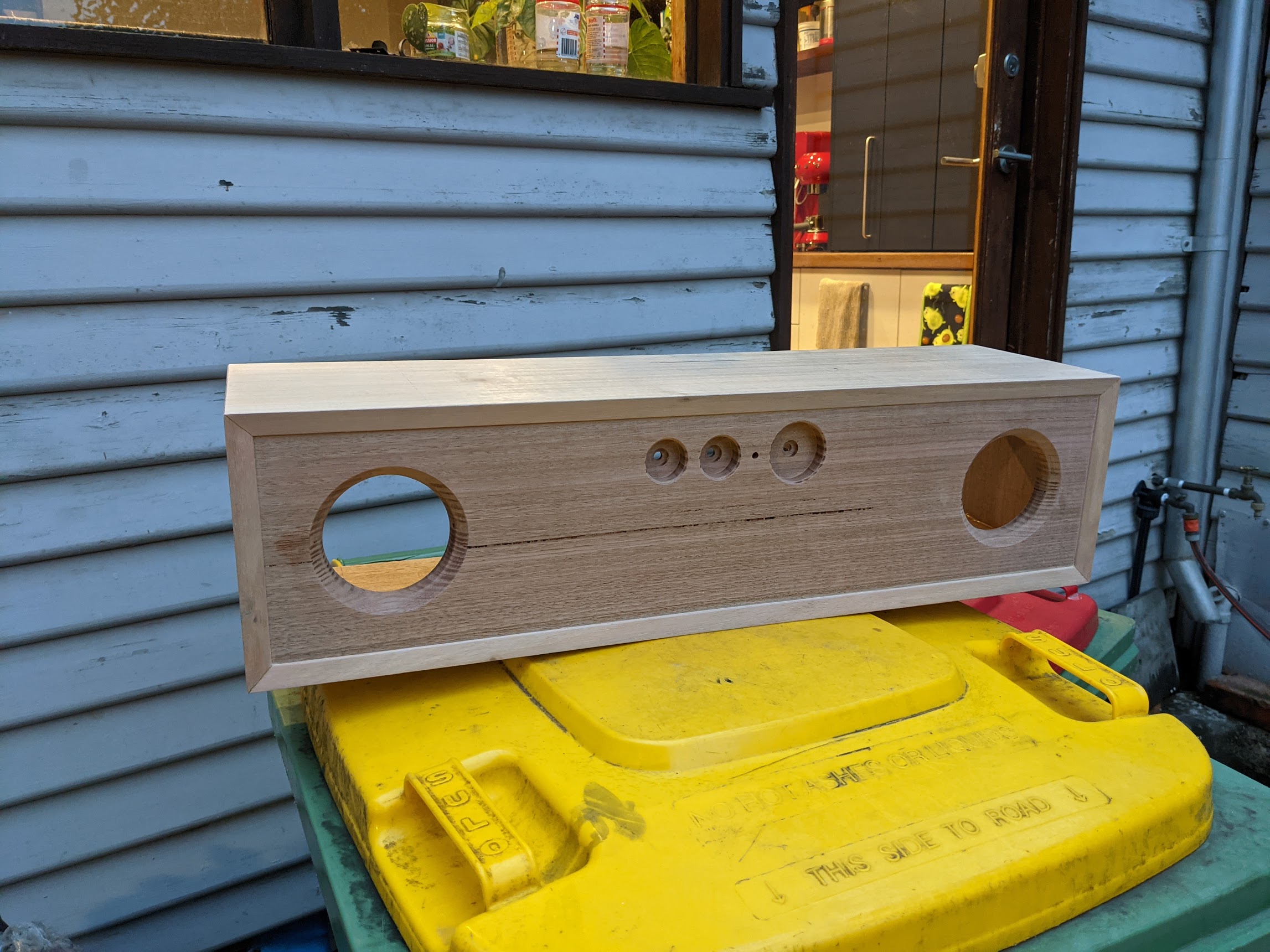
Enclosure assembly:

Test-fit drivers:
Coated with two coats of ‘Wipe-On Polyurethane’:
3D-printed feet to match the knob design:
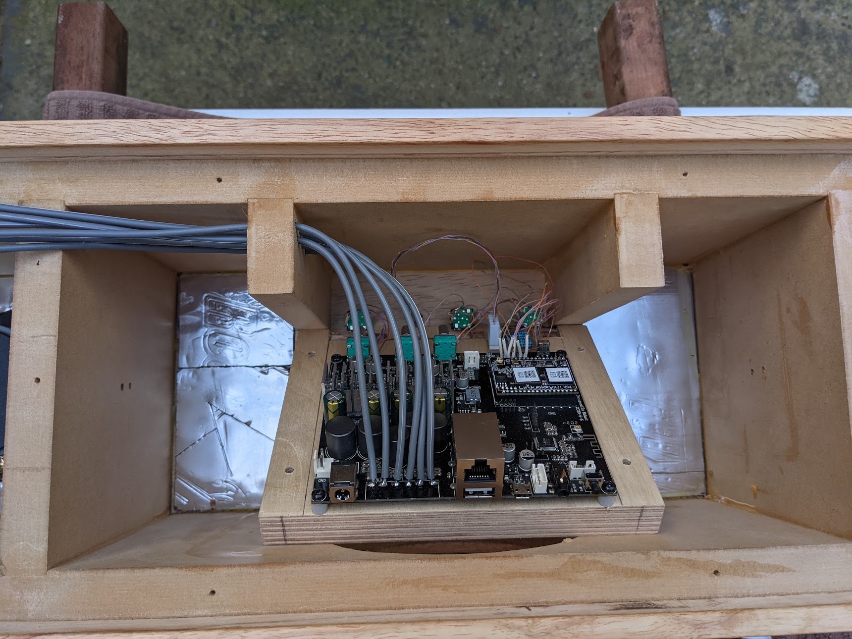
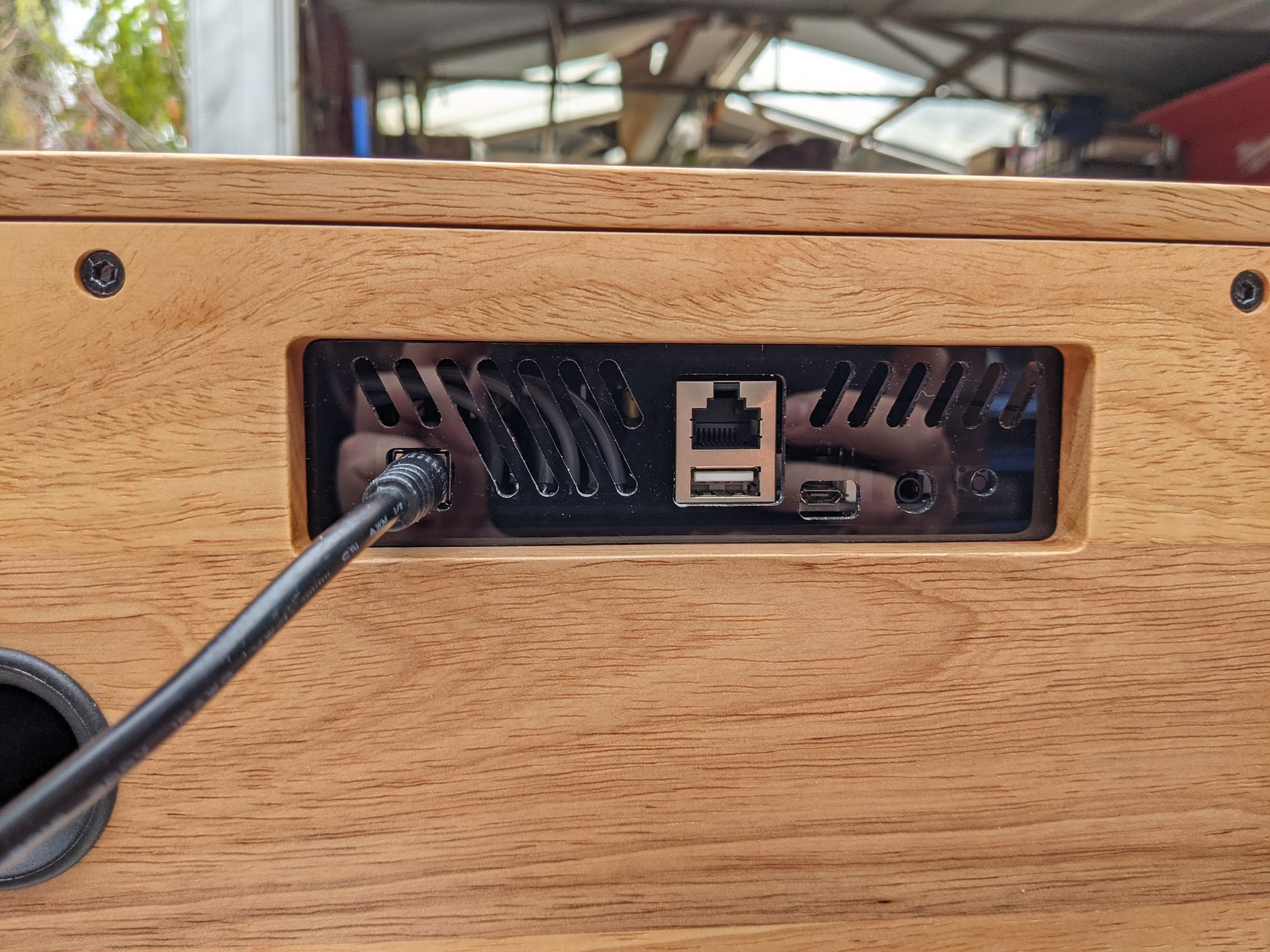
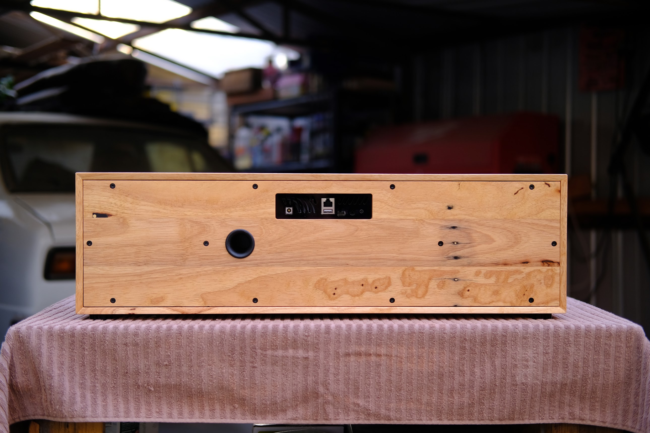
Amp in place with rotary encoders screwed into the front panel. I soldered in new wiring for the speakers (the existing terminals protrude too far out of the back of the amp board and I wanted to keep them hidden. I also made up plate out of 3mm acrylic to cover the rear board and expose the ports:
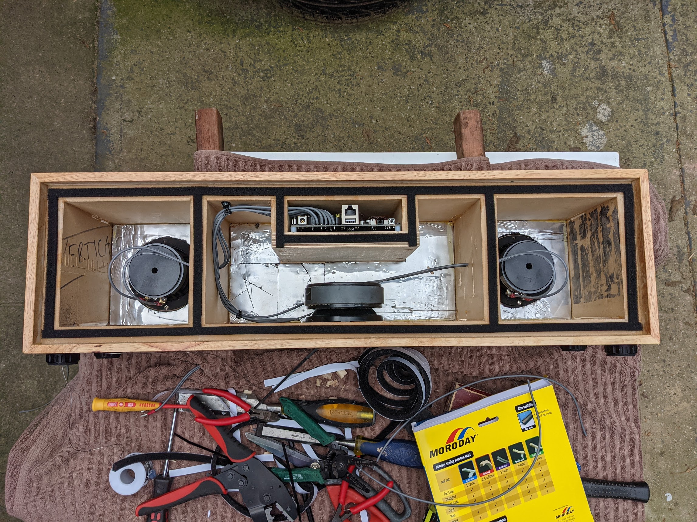

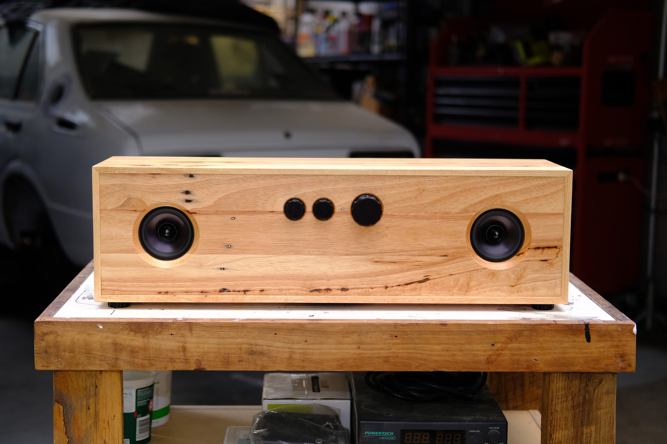
Then final assembly and it’s up and running:
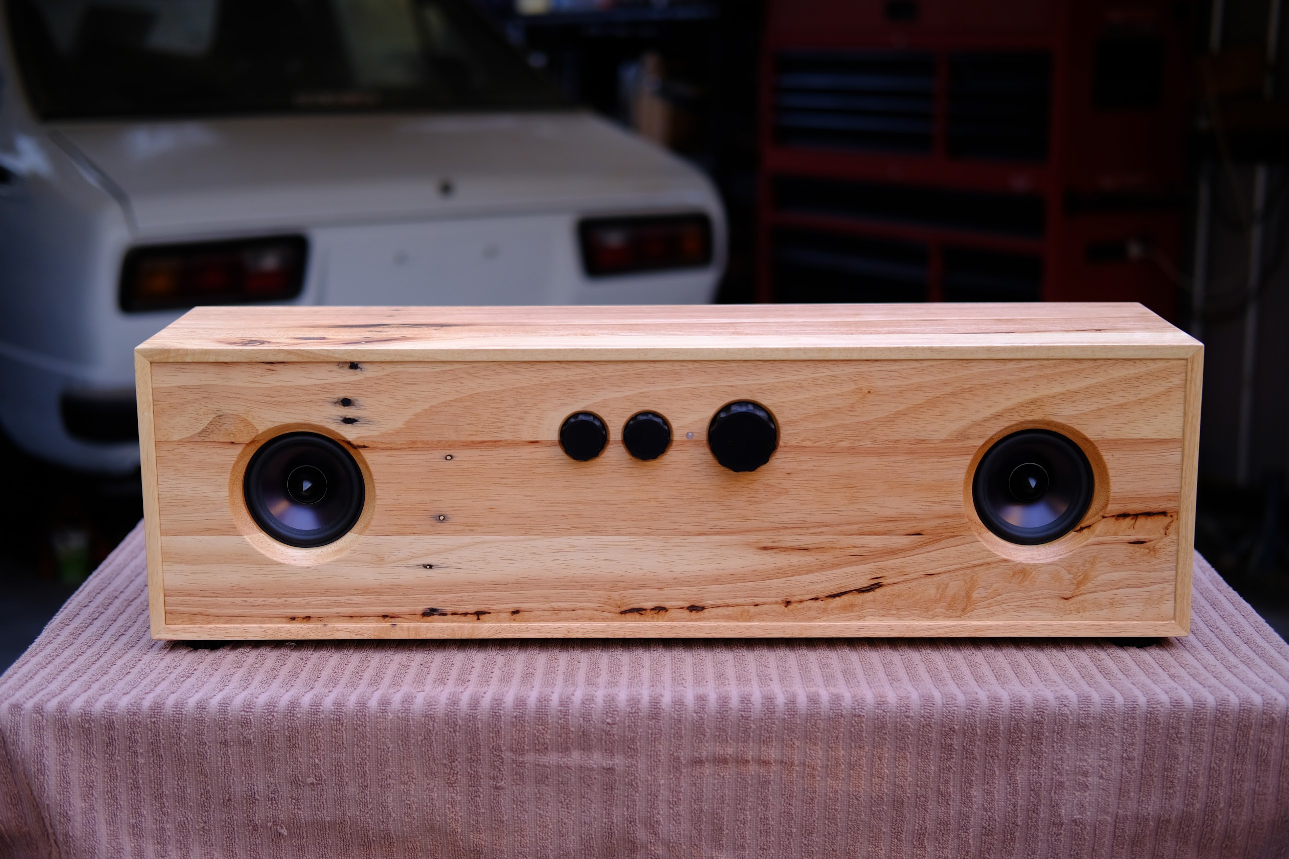

I am very happy with the outcome. The functionality is perfect - I love that the Amp will connect to the home WiFi and I can just use Spotify Connect, then easily skip a song by hitting the middle knob. It can also be paired with a Google Home as a bluetooth speaker, and then set as the default speaker, so Chromecast can play songs directly to it via Google Assistant. Sound quality is also great, surprising bass for it’s size, and I have only scratched the surface of all of the EQ settings via the workbench software. If I ever get around to making V3, it will be with 4 ohm drivers and with an attempt at fitting a slightly bigger bass driver. The choice of the DS135 was originally due to a max depth constraint of 180mm which was a little too small for a 6" driver.
I don’t have many photos from the V1 build - but I found a couple while putting together this post. V1 is a little different, rather than an MDF core, it’s built from solid Tasmanian Oak. Other than slight dimensional changes though, it’s essentially the same:


Cheers, Rob.
 .
. Just a little tip: dont mount the Drivers from behind, cause the Board will mess with the Speakerresponse. Alway try to have the drivers “see” as few edges as possible. With a Umik fe. you could flatten the response and have the speaker sounding a lot better