Hey All.
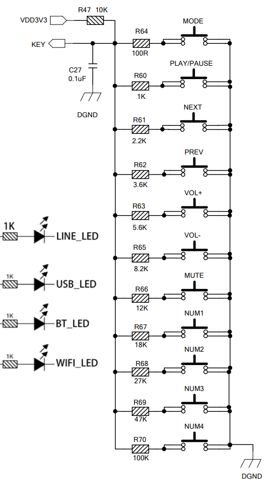
I am getting inconsistent results when attempting to setup the ADC buttons based on the specs:
This applies in my case to the 2.1 amp. The only functions I have managed to successfully implement are:
- On/Off (not documented. discovered by accident)
- Mode
- Play/Payse
- Next
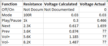
But even these are not perfect. Based on 3.3v supply, I have calculated the following voltages based on the resistor value specified. Note that - applying 0V to ADC seems to switch the amp off/on, the play/pause function is approximately what I would expect, but the the next button needs 1.6v to activate. Then I have been unable to successfully achieve prev/vol-/vol+
Strangely - if connected to WiFi and streaming via Spotify Connect, ‘Next’ works fine at 1.6v. However, if I switch to Bluetooth and disable WiFi, play/pause works at 0.46v but ‘Next’ changes the input back to WiFi.
Either I have completely misread the specs or I am doing something wrong, or it’s not working as expected. I was hoping there may be others who have been trying to setup the adc buttons based on the documentation and might be able to share some outcomes? There are some voltages where I hear the ‘button’ sound from the amp but no function seems to activate. Originally I thought that maybe the specs should have been applicable to a 5v supply - but this doesn’t match up either.
1 Like
Hi Rob,
It’s not your fault, it’s an error in the schematic shown in the manual. I ran into the same problem and determined each resistor individually by trial-and-error (before I knew the solution). Worked for me but was quite some work.
The solution is to not install the 10k pullup resistor (R47). This resistor is already on the board and if you add an additional one externally all the voltages will shift and switch other functions than intended. For reference, see the following post of an Arylic employee regarding this:
https://forum.arylic.com/t/first-speaker-with-up2stream-amp-2-1/362/7
He also promised to change the manual accordingly.
Hope this helps to continue with your project. Would be nice if you could present it here once it’s finished.
Best regards,
Sven
2 Likes
Hey Sven.
Thanks for the reply - this is exactly what I was trying to find! I have spent so much time stuffing about with trial an error to get a semi-functional result, so this is excellent.
This morning I tried again without the 10k pullup and finally it gave me consistent results. Mode, Play/Pause and Next all worked first try. I haven’t tried the rest - the most critical were Play/Pause and Next anyway.
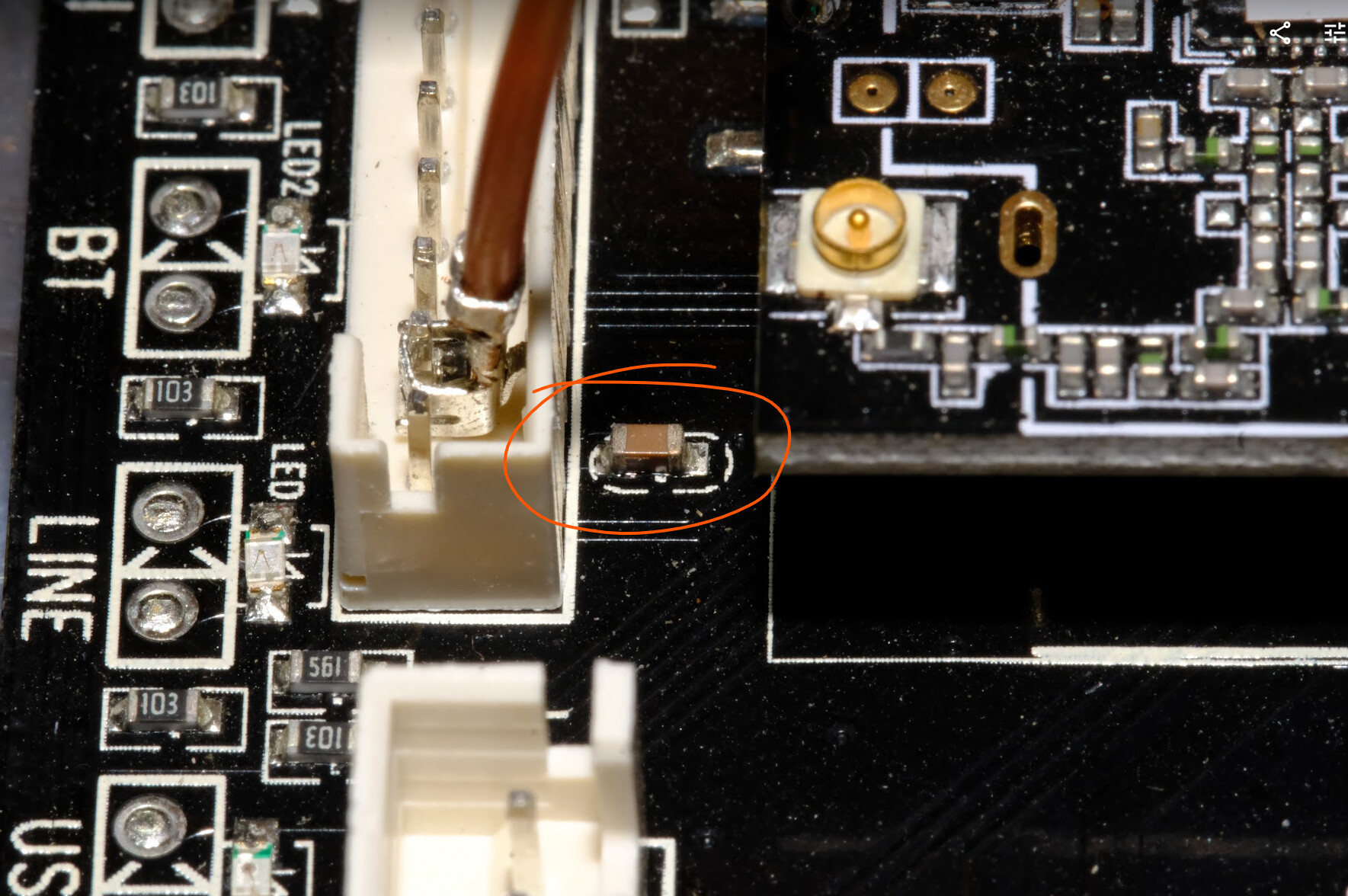
I am fairly certain that the 0.1uF capacitor is also included on the board. I can’t check it’s value, but this capacitor positioned directly next to the ADC pin measures with zero resistance on one side to the ADC pin and zero on the other side to ground:
So, I think the button circuit does not even need the cap externally - just the resistors to ground based on the documented values.
Thanks so much! Hopefully the documentation gets updated so that others don’t have to find out the hard way.
3 Likes